Experimental instrument for parallel axis theorem

An experimental instrument, parallel axis technology, applied in instruments, educational appliances, teaching models, etc., can solve problems such as lack of quantitative verification, and achieve the effect of practicality, convenience, simple and novel structure

Inactive Publication Date: 2014-11-05
JIANGNAN UNIV
View PDF5 Cites 0 Cited by
  • Summary
  • Abstract
  • Description
  • Claims
  • Application Information

AI Technical Summary

Problems solved by technology

In physical experiments, there is a lack of experimental devices to quantitatively verify the above laws

Method used


Image

  • Experimental instrument for parallel axis theorem
  • Experimental instrument for parallel axis theorem
  • Experimental instrument for parallel axis theorem

Examples


Embodiment Construction

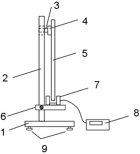
[0013] Such as figure 1 As shown, the vertical pole 2 is vertically fixed on the base 1, a leveling knob 9 is provided under the base 1 for adjusting the level of the base 1, the rotating shaft 3 is horizontally fixed on the vertical pole 2, the head of the rotating shaft 3 is fixed with a magnet 4, and a rigid body 5 It is adsorbed on the magnet 4, and the adsorption point can be selected as required. After the rigid body 5 deviates from the equilibrium position and is released, the rigid body 5 can rotate back and forth around the rotating shaft 3 . The detection platform 6 is movably fixed on the pole 2 and is located below the lowest position of the rigid body 5. The photogate 7 is fixed on the detection platform 6. The photogate 7 is connected with a timer 8 for measuring the rotation period T of the rigid body 5.

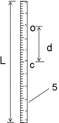
[0014] Such as figure 2 As shown, the rigid body 5 is an iron ruler whose mass m is uniformly distributed, and the surface is provided with reading scribe ...


PUM


Abstract

The invention discloses an experimental instrument for the parallel axis theorem. The experimental instrument comprises a base, an upright which is vertically and fixedly arranged on the base, a rotary shaft, a magnet and a rigid body, wherein the rotary shaft is horizontally fixed on the upright, and the magnet is fixedly arranged at the head of the rotary shaft. The rigid body is made from a magnetic material, so that the rigid body is absorbed on the magnet and can rotate around the rotary shaft. The rotary shaft of the rigid body can be changed through changing the absorption site of the rigid body. The parallel axis theorem can be verified and rotary inertia can also be obtained through measurement of a rotation period of the rigid body. The experimental instrument provided by the invention is simple and novel in structure, practical, convenient, and beneficial for quantitative research of a rotation law of the rigid body.

Description

technical field [0001] The invention belongs to the field of physical experiment instruments, in particular to a parallel axis theorem experiment instrument. Background technique [0002] The period of rotation of a rigid body making a small rotation around a fixed axis is , where m is the mass of the rigid body, d is the distance from the center of mass to the rotation axis, and J is the moment of inertia of the rigid body around the fixed axis. According to the parallel axis theorem: J=J C +md 2 , where J C is the moment of inertia of the rigid body around the axis parallel to the fixed axis and passing through the center of mass, and d is the distance between the two parallel axes. It can be seen from the above formula that when the same rigid body rotates around different rotation axes, its moment of inertia J and rotation period T will change accordingly. In physical experiments, there is a lack of experimental devices to quantitatively verify the above laws. Co...

Claims


Application Information

Patent Timeline
Patent Type & Authority Patents(China)
IPC IPC(8): G09B23/10
Inventor 苗泉龙罗浩陈健彭亚蒙
Owner JIANGNAN UNIV
Why Eureka
Try Eureka