Full-automatic solar power LED road alignment safety guiding and warning lamp device
A safe guidance and fully automatic technology, applied in the directions of roads, roads, road signs, etc., can solve the problems of prone to traffic accidents, unclear contours in straight sections and curves, and achieve the effect of ensuring driving speed.
- Summary
- Abstract
- Description
- Claims
- Application Information
AI Technical Summary
Problems solved by technology
Method used
Image
Examples
specific Embodiment approach 1
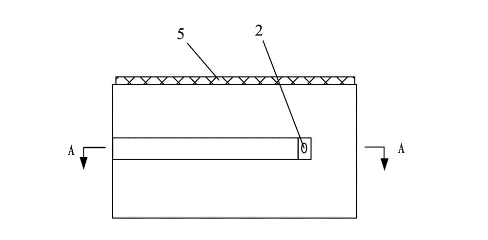
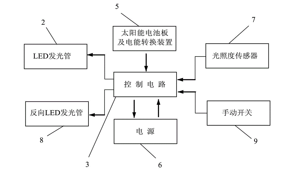
[0007] Specific implementation mode one: the following combination figure 1 This embodiment will be specifically described. This embodiment includes a housing 1, an LED luminous tube 2, a control circuit 3 and a power supply 6, the power supply 6 supplies power to the LED luminous tube 2 through the control circuit 3, and a light guide groove 1 is opened on one side elevation of the housing 1 -1, the LED luminous tube 2 is arranged at one end of the light guide groove 1-1 and the light beam emitted by the LED luminous tube 2 exits along the length direction of the light guide groove 1-1, and the control circuit 3 and the power supply 6 are arranged in the housing 1 .
[0008] The rectangular steel housing 1 of the present embodiment is 400 millimeters long, 200 millimeters wide, 150 millimeters high, and the side facade height is 30 millimeters, and the LED light-emitting tube is a high-power light-emitting tube. Power supply 6 is a 12-volt storage battery.
specific Embodiment approach 2
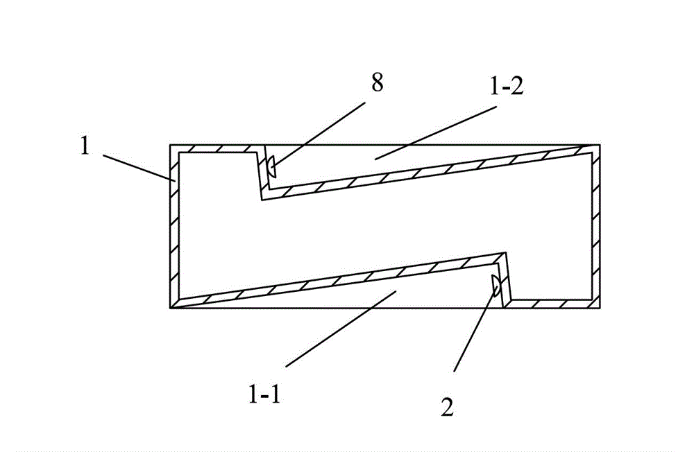
[0009] Specific implementation mode two: the following combination figure 2 This embodiment will be specifically described. Compared with Embodiment 1, the light guide groove 1-1 of this embodiment is parallel to the upper bottom surface and the lower bottom surface of the housing 1 in the horizontal direction, and the depth of the light guide groove 1-1 into the side wall is from one end of the LED light-emitting tube 2 to The depth at the other end gradually becomes shallower until the depth is zero. Such setting conforms to the light direction, and also facilitates the installation of the whole device on the isolation wall. Others are the same as the first embodiment.
specific Embodiment approach 3
[0010] Specific implementation mode three: the following combination figure 2 This embodiment will be specifically described. Compared with the second embodiment, this embodiment also includes a reverse LED light-emitting tube 8, and a reverse light guide groove 1-2 is opened on the other side elevation of the housing 1, and the reverse LED light-emitting tube 8 is arranged on the reverse light guide groove. One end of 1-2 and the light beam emitted by the reverse LED luminous tube 8 emerges along the length direction of the reverse light guide groove 1-2, and the light beam emitted by the reverse LED luminous tube 8 is opposite to the direction of the light beam emitted by the LED luminous tube 2 . With such arrangement, installing one present embodiment on the isolation retaining wall can provide direction indication for the lanes on both sides of the isolation retaining wall. Others are the same as the second embodiment.
PUM
 Abstract
Description
Claims
Application Information
 - R&D
- Intellectual Property
- Life Sciences
- Materials
- Tech Scout
- Unparalleled Data Quality
- Higher Quality Content
- 60% Fewer Hallucinations
Browse by: Latest US Patents, China's latest patents, Technical Efficacy Thesaurus, Application Domain, Technology Topic, Popular Technical Reports.
© 2025 PatSnap. All rights reserved.Legal|Privacy policy|Modern Slavery Act Transparency Statement|Sitemap|About US| Contact US: help@patsnap.com


