Opposite-sliding-block forming mechanism of progressive stamping die

A forming mechanism and progressive die technology, applied in forming tools, metal processing equipment, manufacturing tools, etc., can solve the problems that the forming structure cannot meet the product design structure and precision requirements, the stamping product is small in size, and the production cost is increased. Achieve quality stability, increase performance reliability, and improve production efficiency

Inactive Publication Date: 2013-06-12
KUNSHAN XINTAILI PRECISION COMPONENTS CO LTD
View PDF6 Cites 0 Cited by
  • Summary
  • Abstract
  • Description
  • Claims
  • Application Information

AI Technical Summary

Problems solved by technology

[0003] According to the product structure needs to develop stamping dies that meet the application, and the standardized products have fixed product size and structure due to their small size; therefore, the stamped products are small in size and have strict requirements; the internal forming structure of the existing mold cannot meet its product design structure and accuracy requirements, resulting in a certain technical bottleneck
[0004] as attached figure 1 It is shown that this type of structure is more structurally specific than normal stamping products, and the slider structure commonly used in the market today, such as figure 2 As shown, only one slider 100 is used, it is difficult to complete the structure in the progressive die and meet the requirements of high dimensional accuracy, or the strength of the part is too low and the frequency of replacement is too high, which increases the production cost

Method used


Image

  • Opposite-sliding-block forming mechanism of progressive stamping die
  • Opposite-sliding-block forming mechanism of progressive stamping die
  • Opposite-sliding-block forming mechanism of progressive stamping die

Examples


Embodiment Construction

[0017] The preferred embodiments of the present invention will be described in detail below in conjunction with the accompanying drawings, so that the advantages and features of the present invention can be more easily understood by those skilled in the art, so as to define the protection scope of the present invention more clearly.

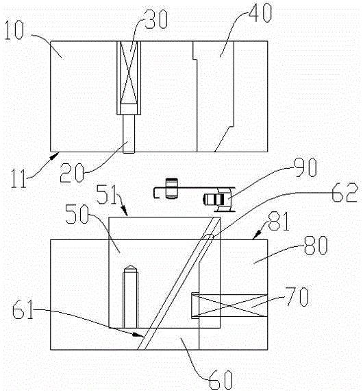
[0018] see image 3 , the embodiment of the present invention includes:

[0019] A stamping progressive die anti-slider forming mechanism, including: middle plate 10, positioning PIN 20, inner spring 30, upper die forming block 40, main slider 50, auxiliary slider 60, return spring 70 and slider seat 80 .

[0020] The main slider 50 and the auxiliary slider 60 are installed in the slider seat 80, and are restricted by first limiting structures such as installation grooves or rails, so that the main slider 50 can only move relative to the slider seat 80. The up and down movement is restricted by the second limiting structure such as the installa...


PUM


Abstract

The invention discloses an opposite-sliding-block forming mechanism of a progressive stamping die. The opposite-sliding-block forming mechanism comprises a middle die plate, an upper die forming block, a main sliding block, an auxiliary sliding block, a restoring spring and a sliding block seat. The opposite-sliding-block forming mechanism of the progressive stamping die adopts dual sliding blocks to conduct bending actions, the main sliding block is used as a carrier, the auxiliary sliding block is used as a forming part, the movement of a complex formed product in the die is completed through the main sliding block and pre-stamping is required to be completed according to the mechanical action of a press; since the two sliding blocks move towards two directions, formed structures which cannot be realized by adopting the existing bending forming method are realized, the production efficiency is improved, the performance reliability is increased and the adjustment and the maintenance are facilitated; and the stable quality of products produced in a large scale is further realized, the development and production costs of a platform and the die are greatly reduced, and the enterprise competitiveness is effectively improved.

Description

technical field [0001] The invention relates to the field of electronic parts manufacturing equipment, in particular to an anti-slider forming mechanism of a stamping progressive die. Background technique [0002] At this stage, the pace of upgrading of electronic products is accelerating, and the supporting electronic components are gradually required to be small in size and powerful in function. Some components are standardized and general-purpose mass production, which further requires high output and long life of some parts. [0003] According to the product structure needs to develop stamping dies that meet the application, and the standardized products have fixed product size and structure due to their small size; therefore, the stamped products are small in size and have strict requirements; the internal forming structure of the existing mold cannot meet its product design structure and accuracy requirements, resulting in a certain technical bottleneck. [0004] as a...

Claims


Application Information

Patent Timeline
Patent Type & Authority Applications(China)
IPC IPC(8): B21D37/10
Inventor 徐航海
Owner KUNSHAN XINTAILI PRECISION COMPONENTS CO LTD
Why Eureka
Try Eureka