Multiple point rectifier with brake chopper

A technology of rectifier and braking resistor, applied in the field of drive, to achieve the effect of reducing overhead and cost

Active Publication Date: 2013-06-05
GE ENERGY POWER CONVERSION
View PDF13 Cites 2 Cited by
  • Summary
  • Abstract
  • Description
  • Claims
  • Application Information

AI Technical Summary

Problems solved by technology

In addition, there may also be operational reasons that the voltage across the intermediate circuit capacitor drops at a certain point in time and converts the energy stored therein into heat

Method used


Image

  • Multiple point rectifier with brake chopper
  • Multiple point rectifier with brake chopper
  • Multiple point rectifier with brake chopper

Examples


Embodiment Construction

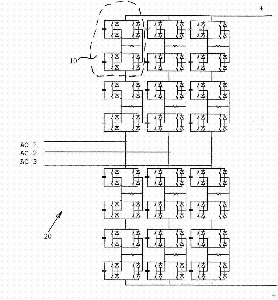
[0024] exist figure 2 A three-phase view of a modular multipoint rectifier 20 is shown in . This type of multipoint converter is also known under the English name "Modular Multilevel Converter" (M2C).

[0025] Each of the three phases of the rectifier 20 is constructed from two parallel circuit configurations. Furthermore, each of the three phases is constituted by a plurality of finisher subsystems 10 , and each phase is constituted by four rectifier subsystems 10 respectively in this embodiment. The individual following references to the rectifier subsystem Figure 1a , 1b explained in more detail.

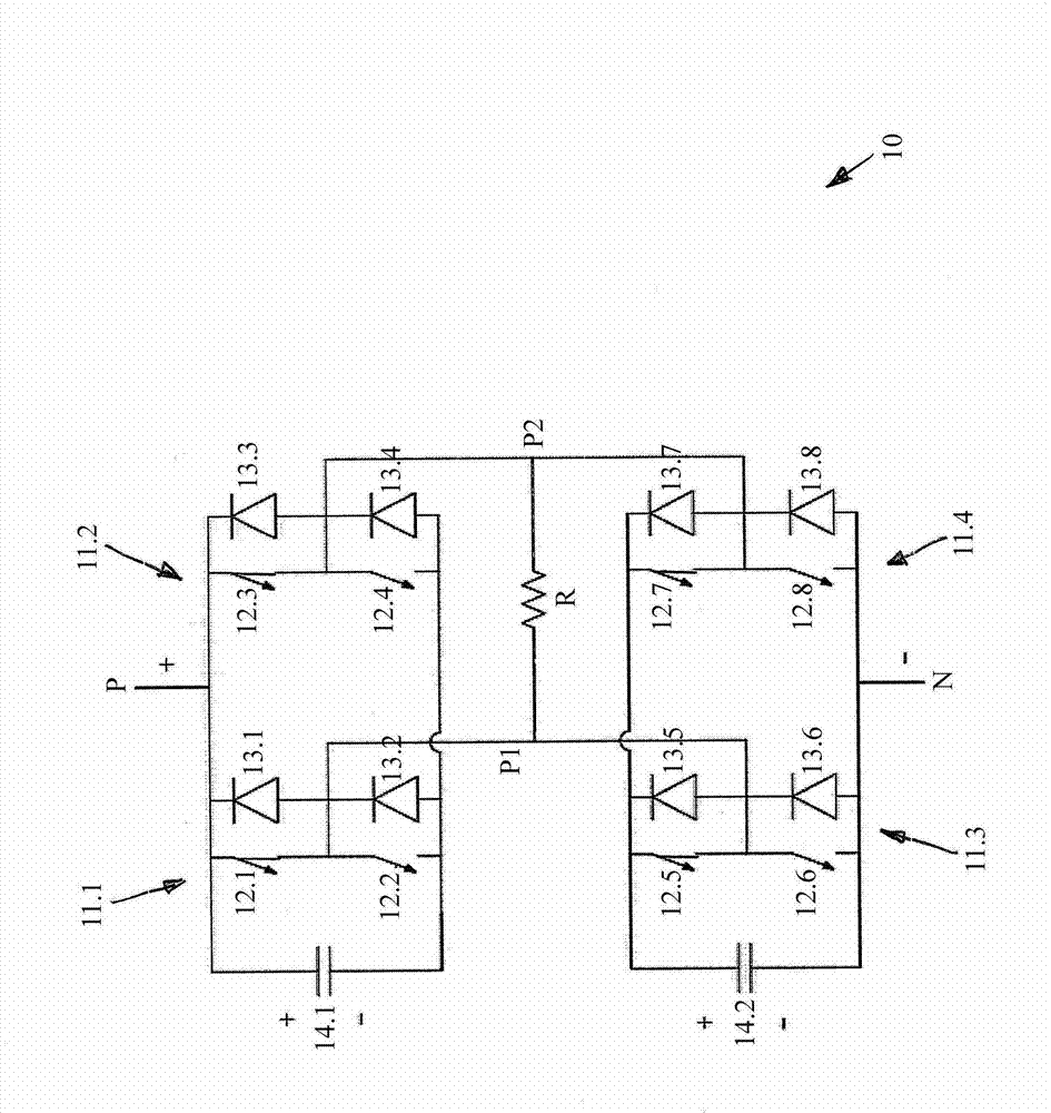
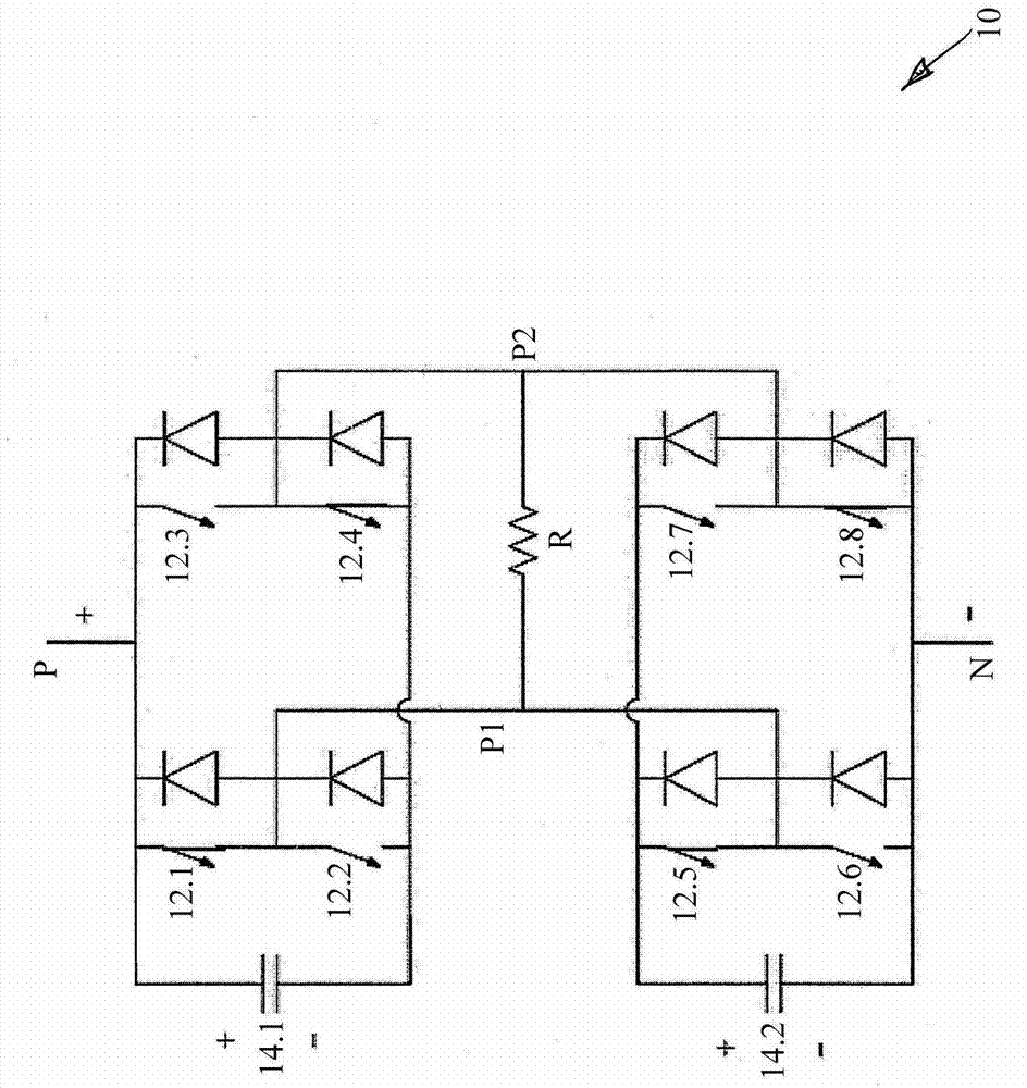
[0026] The rectifier subsystem 10 includes a parallel circuit configuration. The semiconductor switches of each rectifier subsystem and collectively all rectifier subsystems are used to control the operation of the rectifier 20 . The semiconductor switches of each individual rectifier subsystem 21 are used simultaneously and independently of the other rectifier subsystems...


PUM


Abstract

The invention discloses a circuit of a rectifier. The circuit comprises a plurality of semiconductor switches and capacitors for driving the rectifier, and comprises a brake resistor for reducing energy. The resistor is connected with the semiconductor switches without additional switches. The operation of the rectifier and the current of the brake resistor can be controlled by the semiconductor switches.

Description

technical field [0001] The invention relates to a circuit for a rectifier according to the preamble of claim 1 and a method for driving according to claim 9 . Background technique [0002] In the rectifier it may be necessary to convert the excess energy present in the rectifier into heat. The nature of the reasons for this can be varied. It can happen, for example, that an energy source connected to the rectifier (such as a wind power plant) supplies the rectifier with energy, but an energy sink connected to the rectifier elsewhere may not absorb energy (such as the power supply network in the event of a short circuit) or the rectifier Due to its structure it cannot feed energy back into the grid. In rectifiers with a voltage intermediate circuit, this would lead to an impermissible increase in the intermediate circuit voltage, and these energies must be reduced. It is likewise possible that, in certain operating states (depending on load, regulation, configuration) in m...

Claims


Application Information

Patent Timeline
Patent Type & Authority Applications(China)
IPC IPC(8): H02M7/12H02M1/32H02M7/72
CPCY02E10/76B60L7/06H02M1/32H02M7/219H02M5/45H02P3/22H02M7/483Y02T10/642H02M7/217H02M7/4835
Inventor 罗兰·雅各布托马斯·布鲁克纳
Owner GE ENERGY POWER CONVERSION
Why Eureka
Try Eureka