Thin roof ventilator

A kind of ventilator, thin technology, applied in the direction of roof ventilation, ventilation system, space heating and ventilation, etc., can solve the problems of ventilator loss of ventilation capacity, effective flow area reduction, external pollutants falling, etc., to achieve convenient material Regular replacement, simplified manufacturing and installation, and easy product maintenance

Active Publication Date: 2015-06-24
锦州鹏翔电力轻钢设备有限公司
View PDF8 Cites 0 Cited by
  • Summary
  • Abstract
  • Description
  • Claims
  • Application Information

AI Technical Summary

Problems solved by technology

According to the ventilation flow formula Q= mu f m 3 / s, for a ventilation device of a certain specification, the increase of the overlapping degree will reduce the effective flow area F inside the ventilator, and the too low (thin) wind shelter structure will increase the ventilation resistance after increasing the exhaust air circumvention, and the flow coefficient mu Reduced, these methods of strengthening wind shelter all reduce the ventilation flow Q, that is, the ventilation performance of the product decreases
[0005] In order to enhance the wind-shielding performance, CN202501595U discloses an assembled light roof ventilator with a translational valve plate device, but since the valve plate device is located at the air inlet at the bottom of the ventilator , when the valve plate is closed, the ventilator will lose its ventilation ability, and external pollutants are more likely to fall on the valve plate with the wind, and the falling snowflakes will melt and drip into the building, causing pollution in the building

Method used


Image

  • Thin roof ventilator
  • Thin roof ventilator
  • Thin roof ventilator

Examples


Embodiment Construction

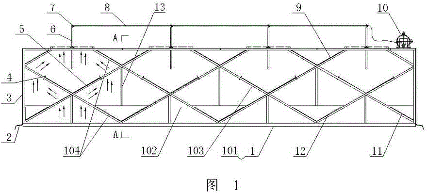
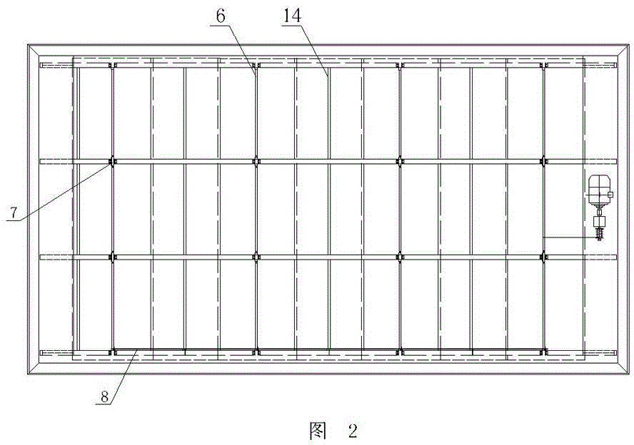
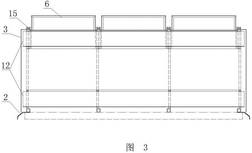
[0025] As shown in the figure, the thin roof ventilator includes multiple rows of parallel structural trusses 1 arranged on the roof vents. In this embodiment, four rows of structural trusses 1 are taken as an example. Rods 14 are connected, outer guard plates 3 are arranged around the multi-row structural trusses 1, flashing boards 2 are respectively arranged at the bottom of the multi-row structural trusses 1, and the flashings located at both ends of the structural trusses 1 The plate 2 is integrated with the outer guard plate 3 .

[0026] The structural truss 1 is composed of a lower cross bar 101 and a plurality of ventilation units 102 connected by profiles on the lower cross bar 101 , and this embodiment takes four ventilation units 102 as an example. The structural truss 1 is located between adjacent ventilation units 102 to form at least a triple V-shaped overlapping structure through its own profiles. In this embodiment, the triple V-shaped overlapping structure is f...


PUM


Abstract

Disclosed is a trussed, natural lighting and ventilating skylight, comprising multiple rows of parallel structural trusses (1), an outer protective panel (3) provided all around the multiple rows of structural trusses (1), multiple ventilation units (102) provided for each row of structural trusses (1), an intermediate layer of V-shaped weatherboard (5) connected between each line of positionally opposing ventilation units (102), a partition panel (13), an upper layer of V-shaped weatherboard (9) and a V-shaped water collecting sump (12) respectively provided between two adjacent lines of ventilation units (102), and a wind-shielding valve plate (6) respectively hinged on two adjacent rows of structural trusses (1). The ventilating skylight can save on material, is easily standardized, has an automatic wind shielding and regulating function against the force of the wind, and can ventilate and provide natural lighting to a large area of a building. The wind-shielding valve plate can be instantly and automatically opened, thereby ensuring a fast and large amount of ventilation and fume extraction.

Description

technical field [0001] The invention relates to a building energy-saving ventilation device, in particular to a thin roof ventilator. Background technique [0002] The demand for building energy-saving applications has stimulated the development and application of building natural ventilation technology products. In recent years, thin roof ventilators have gradually been selected by certain designs and users. A kind of roof ultra-thin streamline ventilator disclosed by CN201589368U and a kind of assembled light roof ventilator etc. disclosed by CN202501595U. [0003] However, the development of conversion technology has gradually become erroneous, and the original simple and economical natural ventilation product technology tends to be complicated: 1. The board molded special-shaped material technology used is not conducive to product standardization, popularization and popularization, and is not conducive to product material selection It is interchangeable with applicat...

Claims


Application Information

Patent Timeline
Patent Type & Authority Patents(China)
IPC IPC(8): F24F7/02F24F13/32E04D13/17
CPCE04D13/03E04D13/0325F24F7/02
Inventor 单连勤卢彤彤单晓晴宋凯宇刘可杨立年
Owner 锦州鹏翔电力轻钢设备有限公司
Why Eureka
Try Eureka