Monitor fixing device

A fixed structure and monitor technology, applied in the direction of supporting machines, mechanical equipment, etc., can solve the problems of easy vibration, unfavorable monitoring use, easy loosening of buckle structure, etc., to achieve the effect of improving stability and effectiveness, and improving monitoring performance

Inactive Publication Date: 2013-06-05
HONG FU JIN PRECISION IND (SHENZHEN) CO LTD +1
View PDF6 Cites 1 Cited by
  • Summary
  • Abstract
  • Description
  • Claims
  • Application Information

AI Technical Summary

Problems solved by technology

However, the fastening method is easily affected by vibration or external force, which makes the fastening structure easy to loosen and unfavorable for monitoring and use. It should be further improved.

Method used


Image

  • Monitor fixing device
  • Monitor fixing device
  • Monitor fixing device

Examples


Embodiment Construction

[0014] The present invention will be described in detail below in conjunction with the accompanying drawings.

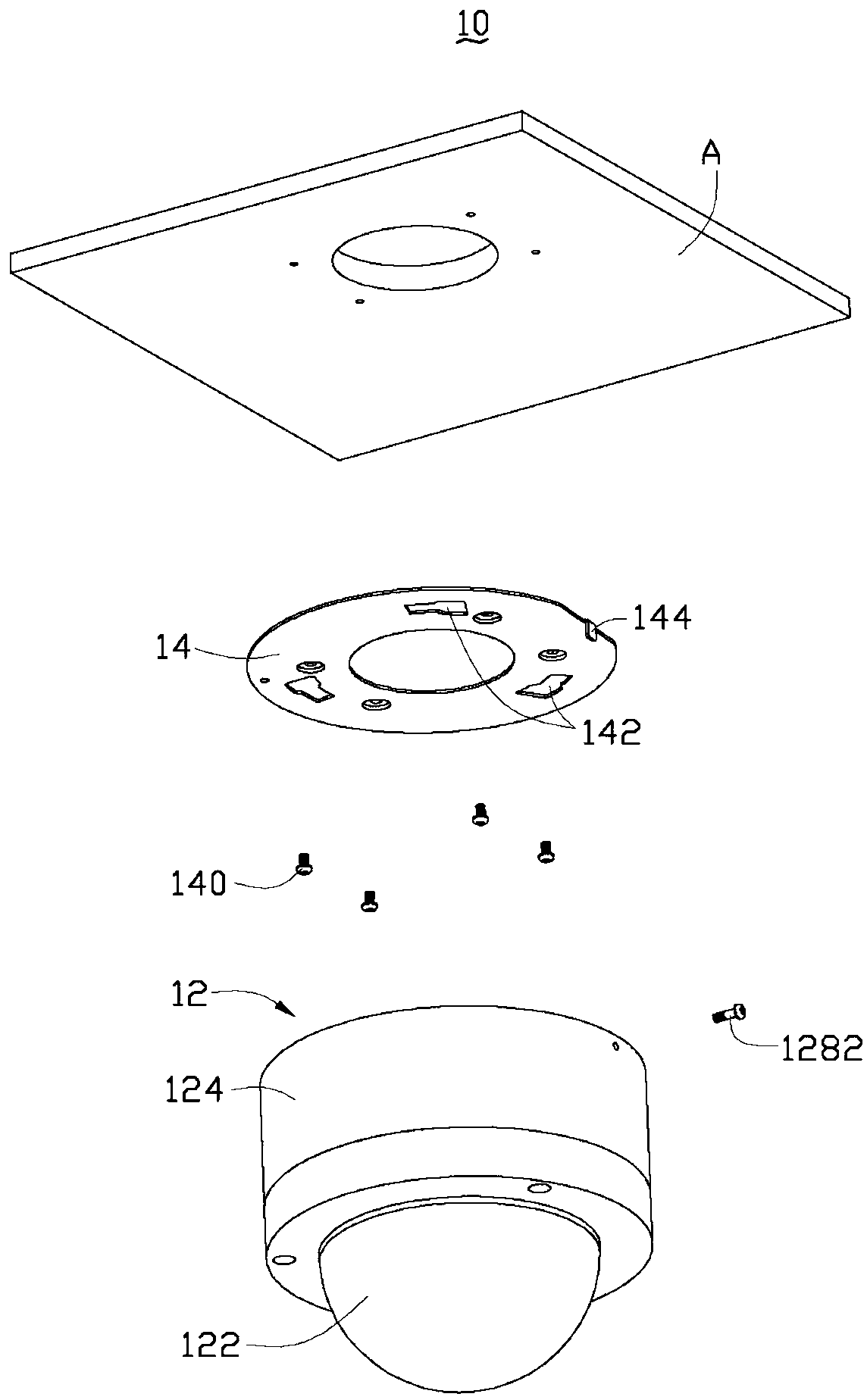
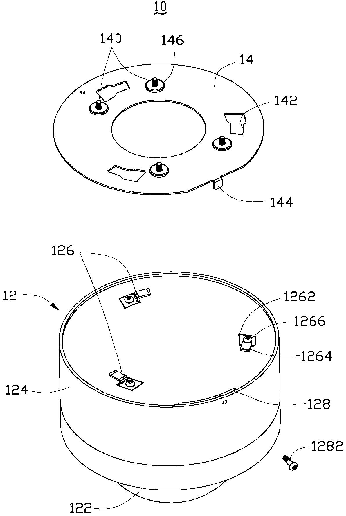
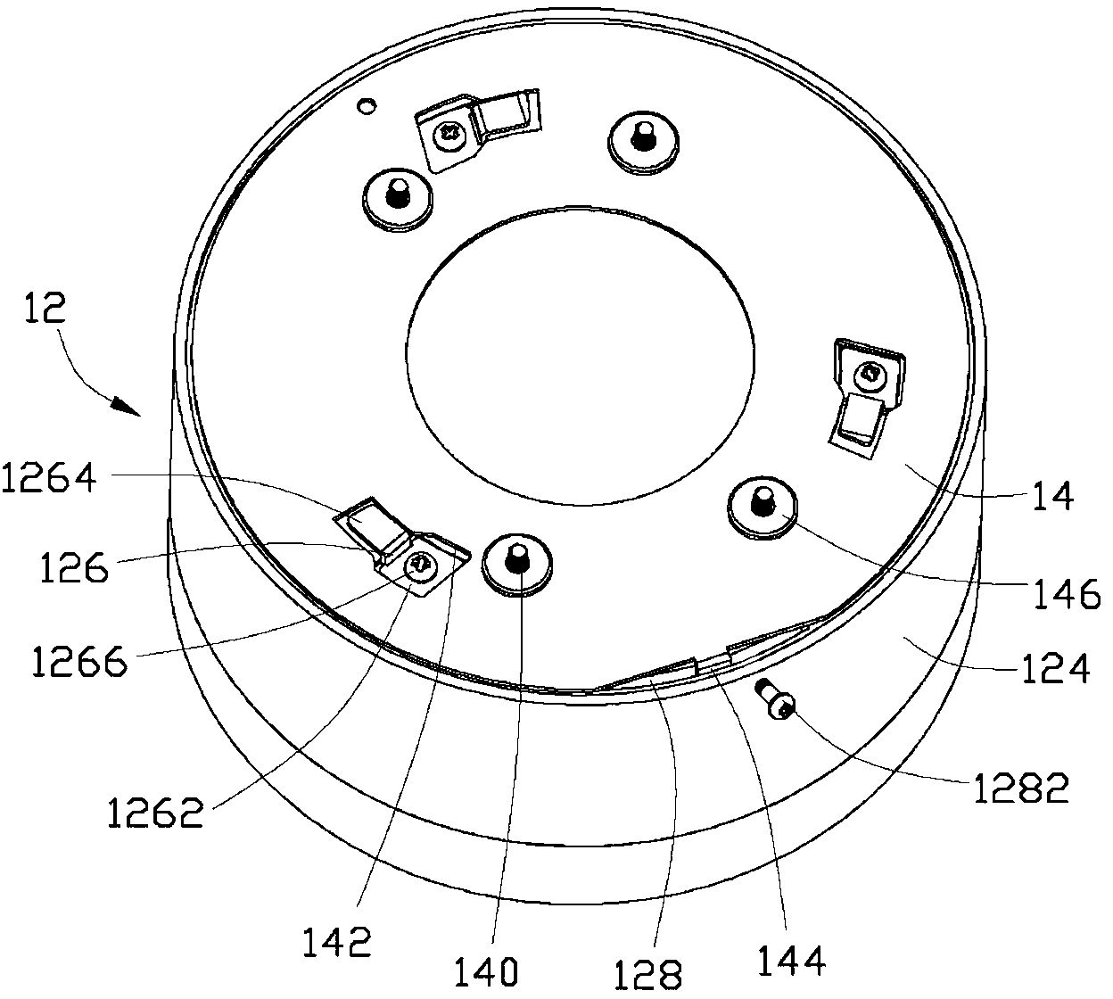
[0015] see figure 1 , is an exploded schematic view of an embodiment of the monitor fixing structure of the present invention. The fixing structure 10 includes a monitor 12 and a fixing plate 14 .

[0016] The monitor 12 includes a lens module 122 and a base 124 , the lens module 122 has an imaging lens and an adjustment base (not shown in the figure). The imaging lens is disposed on the adjustment base, and the adjustment base is disposed on the base 124 . The adjustment base can perform multi-axial rotation on the base 124 , so that the imaging lens can be adjusted along with the adjustment base, so as to expand the monitoring range of the image captured by the imaging lens. In this embodiment, the monitor 12 is fixed on the top surface A of the ceiling through the fixing plate 14, and the fixing plate 14 is firstly locked on the top surface A of the ceiling wit...


PUM


Abstract

The invention provides a monitor fixing device which comprises a monitor and a fixing plate, a plurality of clamp sheets and a locating groove are arranged on a bottom face of the monitor, the clamp sheets are clamped with corresponding groove holes on the fixing plate in a mutual embedding mode, the fixing plate is provided with a locating sheet correspondingly inserted into locating groove, and the locating groove is provided with a stopping component for limiting the locating sheet. The position of the locating sheet is limited, so that firm connection of the monitor and the fixing plate can be maintained.

Description

technical field [0001] The invention relates to a monitor fixing structure, in particular to a monitor fixing structure which can avoid being loosened by vibration or external force. Background technique [0002] Since the imaging lens has been modularized, it has been widely used in daily life, such as portable 3C electronic products, video recording devices, and monitoring devices. The imaging lens module mainly includes a lens, an image sensor and a circuit substrate, wherein the lens can adjust its imaging range through the optical design of the optical lens. At present, in the setting of the monitoring device when it is used, in order to obtain the required clear and stable images, the monitoring device needs to be fixed, but the general monitoring device fixing structure is complicated, and many locking components are required in addition to the support frame, resulting in assembly. inconvenience and increased cost. Therefore, recently, there is an improved monitorin...

Claims


Application Information

Patent Timeline
IPC IPC(8): F16M13/02
Inventor 王少宏马丰阳
Owner HONG FU JIN PRECISION IND (SHENZHEN) CO LTD
Why Eureka
Try Eureka