Guide bar structure in warp knitting machine, knitting machine and thread guide set

A warp knitting machine and yarn guide technology, which is applied in the field of warp knitting machines, can solve the problems of pattern design limitation and inability to avoid each other, and achieve the effect of rich pattern design and simple structure

Active Publication Date: 2013-06-05
KARL MAYER CHINA
View PDF4 Cites 6 Cited by
  • Summary
  • Abstract
  • Description
  • Claims
  • Application Information

AI Technical Summary

Problems solved by technology

The yarn guides arranged in the same traversing row cannot avoid each other during the traversing process, which results in the limitation of pattern design

Method used


Image

  • Guide bar structure in warp knitting machine, knitting machine and thread guide set
  • Guide bar structure in warp knitting machine, knitting machine and thread guide set
  • Guide bar structure in warp knitting machine, knitting machine and thread guide set

Examples


Embodiment Construction

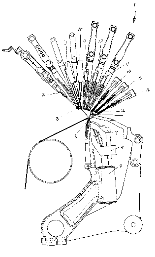
[0026] figure 1 The shown warp knitting machine 1 has a bottom bar 2 with a plurality of guide needles 3 arranged in succession perpendicular to the plane of the paper. Also provided is a needle bed 4 with knitting needles 5 . A knocker comb 6 is arranged adjacent to the knitting needles 5 . A needle core bed 7 cooperates with knitting needles 5 . The needle bed 4 is guided by a guide 8 .

[0027] The structure and mode of operation of this type of warp knitting machine are widely known and will not be further described here.

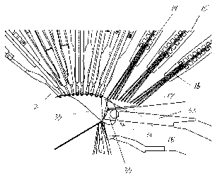
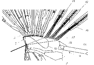
[0028] Also be provided with other combs except bottom comb 2, comb one 9, comb two 10. In addition, a plurality of traversing columns are provided, such as the first traversing column 11 , the second traversing column 12 , and the third traversing column 13 .

[0029] In addition, the warp knitting machine 1 also has other traversing columns, such as traversing columns four 14, traversing columns five 15, and traversing columns six 16, and these t...


PUM


Abstract

The invention relates to the technical field of a warp knitting machine, in particular to a guide bar structure in the warp knitting machine, the warp knitting machine and a thread guide set. The guide bar structure comprises at least one lateral-moving row. The lateral-moving row is provided with the thread guide set which is arranged in a common supporting device. Each thread guide row is capable of moving along a lateral-moving direction. The thread guide set is composed of at least one long belt which is arranged in the supporting device. A hole section is arranged on the lower portion of the long belt. At least one thread guide hole is formed in the hole section side by side along the lateral-moving direction. Extensions are arranged on the long belt extends along the lateral-moving direction, and extensions are arranged between the lower portion of a supporting section in the supporting device and the hole section of the thread guide hole. The guide bar structure, the warp knitting machine with the guide bar structure and the thread guide set on a guide bar all enable the existing monotonous warp knitting machine weaving to be provided with abundant pattern design, and are simple in structure.

Description

technical field [0001] The invention relates to the technical field of warp knitting machines, in particular to a bar structure on a warp knitting machine, a warp knitting machine and a yarn guide group. Background technique [0002] A comb structure of this type is disclosed in Chinese patent CN02127580. In this bar structure, the yarn guide hole is arranged at the end of the yarn guide. Each yarn guide is fastened to a drive element which is movable in a guide groove of the support device. Each driving element thus drives a group of yarn guides fixed thereon to move together, and the arrangement of these yarn guides is determined according to the pattern required. In order to be able to use as many yarn guide groups as possible on the machine, several yarn guide groups are arranged together in the same traversing row. The yarn guides arranged in the same traversing row cannot avoid each other during the traversing process, thus causing limitations on pattern design. C...

Claims


Application Information

Patent Timeline
Patent Type & Authority Applications(China)
IPC IPC(8): D04B27/24
Inventor K·米斯塔
Owner KARL MAYER CHINA
Why Eureka
Try Eureka