
Sodium-sulfur battery

A sodium-sulfur battery and sodium storage tube technology, which is applied in the field of energy storage, can solve the problems of limiting the flow rate of liquid sodium, the length deviation of ceramic electrolyte tubes, and high dimensional accuracy requirements, so as to reduce the dimensional accuracy requirements, reduce the probability of rupture, and reduce the The effect of manufacturing cost

Active Publication Date: 2013-05-29
上海电气企业发展有限公司
View PDF8 Cites 7 Cited by
  • Summary
  • Abstract
  • Description
  • Claims
  • Application Information

AI Technical Summary

Problems solved by technology

Once the ceramic electrolyte tube has microcracks or breaks, the liquid sodium and liquid sulfur will directly contact and react violently, the temperature can reach up to 2000 ° C, and instantly melt the metal parts such as the sodium storage tube in the sodium-sulfur battery, resulting in liquid sodium and liquid sulfur. the leak
[0003] The existing sodium-sulfur battery is mainly composed of a metal case, a ceramic electrolyte tube and a sodium storage tube. In addition, liquid sodium and liquid sulfur serve as active materials, the metal case serves as a current collector and stores liquid sulfur, and the sodium storage tube is a storage container for liquid sodium. and limit the flow rate of liquid sodium
The safety structure of the existing sodium-sulfur battery mainly utilizes the difference between the expansion coefficients of the ceramic electrolyte tube and the sodium storage tube. When the temperature of the sodium-sulfur battery rises, the expansion degree of the sodium storage tube is greater than that of the ceramic electrolyte tube. The gap between the outer wall of the tube and the inner wall of the ceramic electrolyte tube is closed, and the liquid sodium in the sodium storage tube no longer flows into the gap, limiting the reaction of liquid sodium and liquid sulfur, but once the temperature drops, the liquid sodium and liquid sulfur will continue to react, and the fatigue strength of the sodium storage tube is reduced
The bottom surface of the existing ceramic electrolyte tube and the bottom surface of the sodium storage tube are all hemispherical, and there is a certain tolerance in their roundness. At the same time, there is a certain deviation in the length of the ceramic electrolyte tube. The gap between the inner wall of the ceramic electrolyte tube and the inner wall of the ceramic electrolyte tube is difficult to be effectively closed. At the same time, the bottom surface of the sodium storage tube also produces compressive stress on the bottom surface of the inner wall of the ceramic electrolyte tube. Once the ceramic electrolyte tube ruptures, the sodium storage tube is damaged, and a large amount of liquid sodium It flows directly from the through hole at the bottom of the sodium storage tube and reacts violently with liquid sulfur
Therefore, the dimensional accuracy of the ceramic electrolyte tube in the prior art is very high, which increases the manufacturing cost of the sodium-sulfur battery.

Method used


Image

  • Sodium-sulfur battery
  • Sodium-sulfur battery

Examples


Embodiment 1

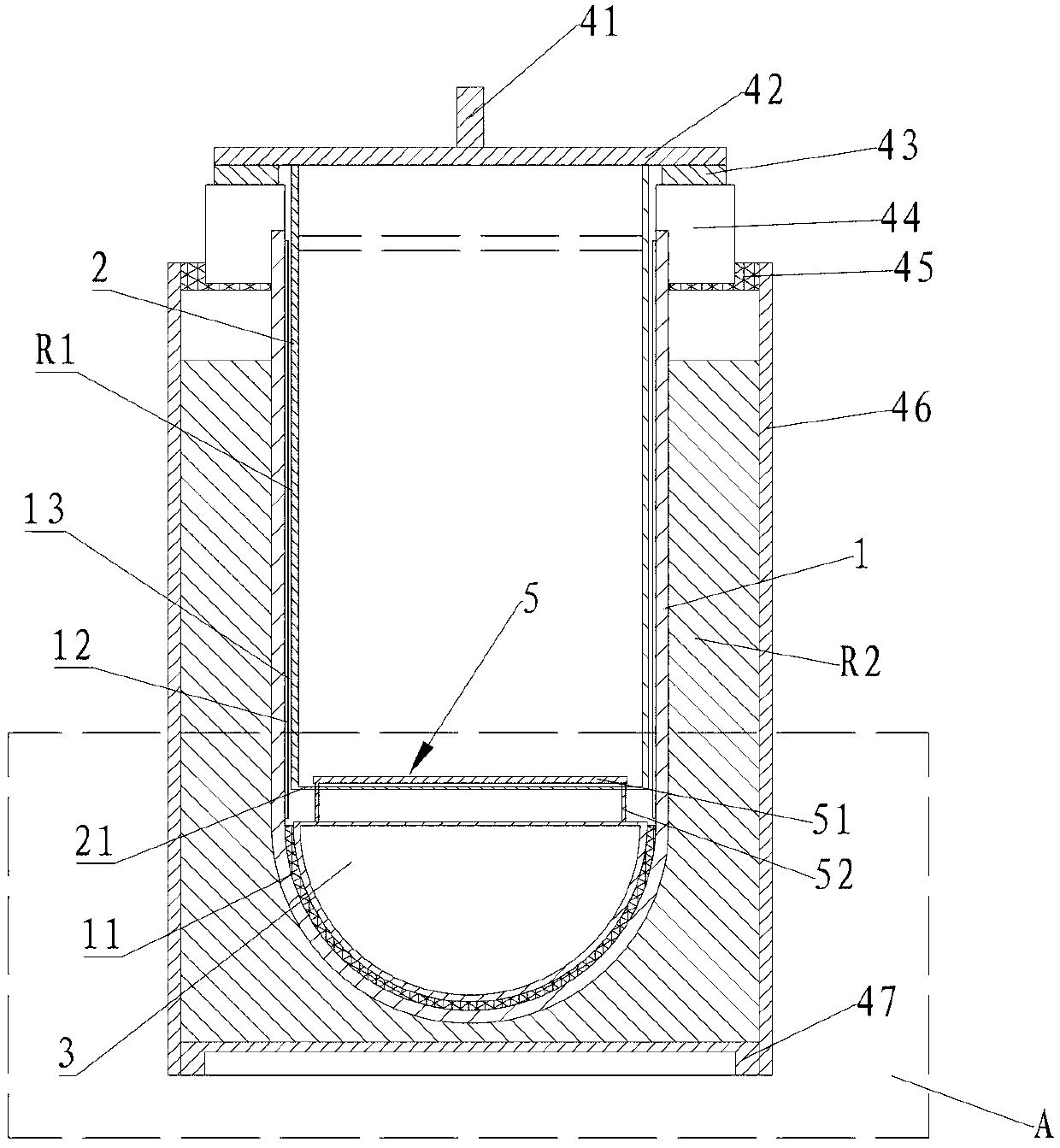
[0018] A sodium-sulfur battery of the present invention comprises a ceramic electrolyte tube 1 and a sodium storage tube 2 sleeved in the ceramic electrolyte tube 1, an annular gap is formed between the sodium storage tube 2 and the ceramic electrolyte tube 1, and the gap is filled with sodium-sulfur The cathode chamber R1 of the battery.

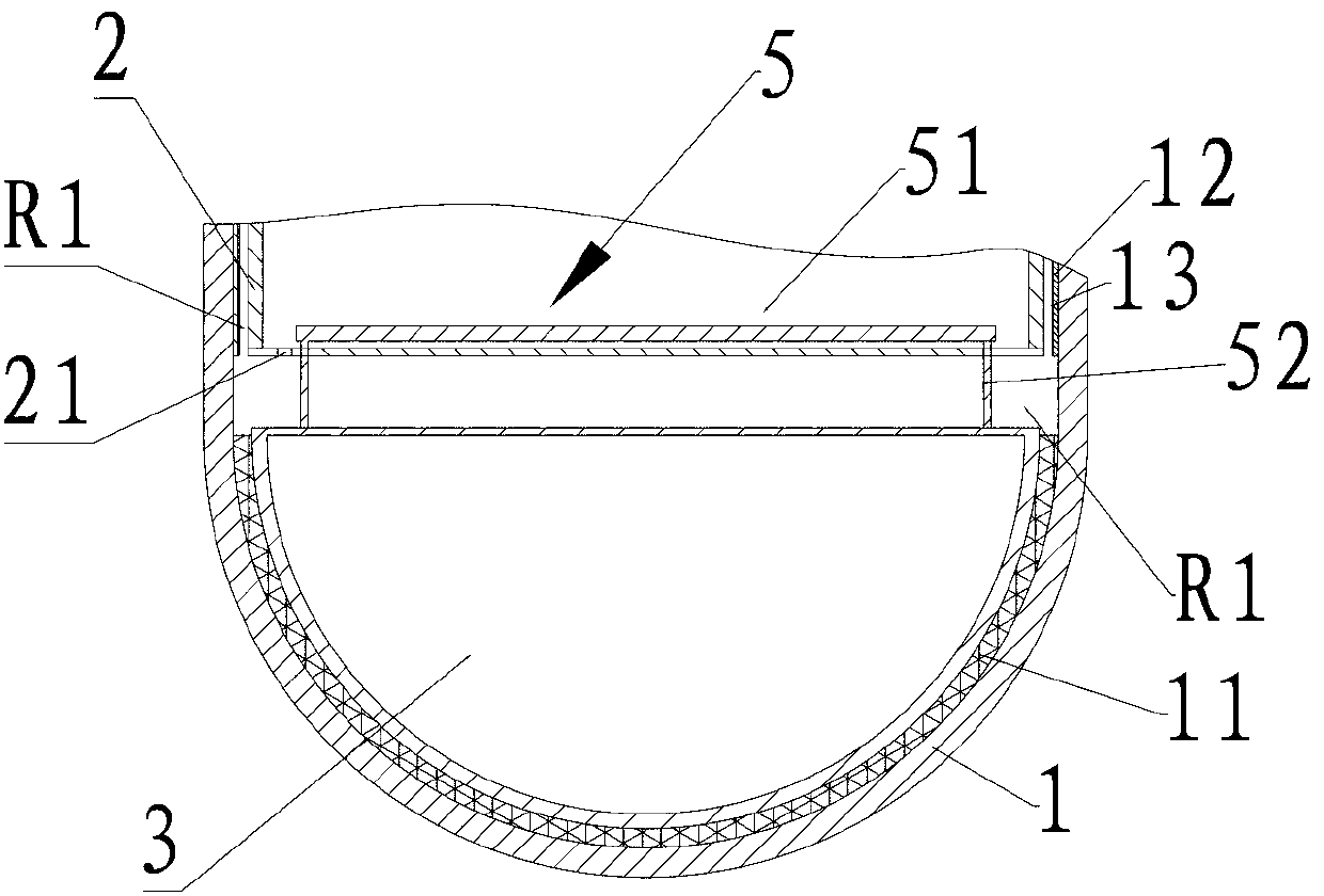
[0019] The bottom surface of the sodium storage tube 2 is flat, and the bottom surface of the sodium storage tube 2 is provided with at least one through hole 21, and the sodium storage tube hemisphere 3 is provided directly below the sodium storage tube 2, and the sodium storage tube hemisphere 3 is connected with the sodium storage tube. There is a gap between the bottom surfaces of the tubes 2, so that the liquid sodium in the sodium storage tube 2 can flow out along the through hole 21 positioned at the bottom surface of the sodium storage tube 2. A fiber buffer layer 11 is provided between the bottom surface of the hemisphere 3 of the ...

Embodiment 2

[0022] see figure 1 , Embodiment 2 is a further improvement on the basis of Embodiment 1. The improvement is that a metal fiber cloth 12 that is close to the inner wall of the ceramic electrolyte tube 1 is provided in the cathode chamber R1, and a metal fiber cloth 12 that is close to the metal fiber cloth 12 Metal foil 13 on the surface. The metal fiber cloth 12 is wet to liquid sodium. Metal foil 13 still has good elasticity at 300°C. The metal fiber cloth 12 has good wettability with liquid sodium at 300°C. At the same time, because the inner wall of the ceramic electrolyte tube 1 has a certain roundness tolerance and the surface is uneven, the metal fiber cloth 12 can make up for the inner wall of the ceramic electrolyte tube 1. roundness tolerance and surface unevenness. Coupled with the elastic effect of the metal foil 13, a number of capillary gaps (not shown in the figure) parallel to the axial direction of the ceramic electrolyte tube 1 are formed between the metal...

Embodiment 3

[0025]Embodiment 3 is a further improvement on embodiment 1 or 2. In embodiment 3, a guide mechanism 5 is provided between the sodium storage tube hemisphere 3 and the sodium storage tube 2, and the guide mechanism 5 includes a piece located in the sodium storage tube 2 Dividing plate 51, and the guiding part 52 that connects dividing plate 51 and sodium storage tube hemisphere 3 top surfaces, in the present embodiment, guiding part 52 is the annulus that connects dividing plate 51 and sodium storage tube hemisphere 3 top surfaces, When the sodium storage tube 2 expands, the ring accurately locates the trajectory of the bottom surface of the sodium storage tube 2, so that the bottom surface of the sodium storage tube 2 drops vertically along the ring, and finally the top surface of the sodium storage tube hemisphere 3 moves the sodium storage tube The through hole 21 on the bottom surface of 2 is closed, and liquid sodium no longer flows out from the through hole 21 on the bott...


PUM

PropertyMeasurementUnit
thicknessaaaaaaaaaa

Abstract

The invention discloses a sodium-sulfur battery in the field of energy storage. The sodium-sulfur battery comprises a ceramic electrolyte tube and a sodium storage tube which is sleeved inside the ceramic electrolyte tube, wherein the bottom surface of the sodium storage tube is provided with at least one through hole, a cathode chamber of the sodium-sulfur battery is formed between the sodium storage tube and the ceramic electrolyte tube, the bottom surface of the sodium storage tube is flat, a sodium storage tube hemispherical body is arranged right below the sodium storage tube, a gap is reserved between the sodium storage tube and the sodium storage tube hemispherical body, a fiber buffer layer is arranged between the bottom surfaces of the sodium storage tube hemispherical body and the inner wall of the ceramic electrolyte tube, and the fiber buffer layer is free from wetting liquid sodium. The sodium-sulfur battery has beneficial effects that under the situation that the through hole in the bottom surface of the sodium storage tube can be effectively sealed, the requirement on the dimensional precision of the ceramic electrolyte tube can be lowered, and the manufacturing cost of the sodium-sulfur battery can be reduced.

Description

technical field [0001] The invention relates to a sodium-sulfur battery in the field of energy storage. Background technique [0002] The core key component of sodium-sulfur battery is β”-Al 2 o 3 Made of ceramic electrolyte tubes, the cycle life of sodium-sulfur batteries depends largely on the quality of ceramic electrolyte tubes. Once the ceramic electrolyte tube has microcracks or breaks, the liquid sodium and liquid sulfur will directly contact and react violently, the temperature can reach up to 2000 ° C, and instantly melt the metal parts such as the sodium storage tube in the sodium-sulfur battery, resulting in liquid sodium and liquid sulfur. of leaks. [0003] The existing sodium-sulfur battery is mainly composed of a metal case, a ceramic electrolyte tube and a sodium storage tube. In addition, liquid sodium and liquid sulfur serve as active materials, the metal case serves as a current collector and stores liquid sulfur, and the sodium storage tube is a storag...

Claims


Application Information

Patent Timeline
Patent Type & Authority Applications(China)
IPC IPC(8): H01M10/39
CPCY02E60/12Y02E60/10
Inventor 龚明光刘宇茅雁祝铭周日生陆志清
Owner 上海电气企业发展有限公司
Learn More