Evaporative-type condenser and heat source device of the same

An evaporative condenser and heat source technology, applied in evaporators/condensers, refrigerators, refrigeration components, etc., can solve the problems of insufficient heat exchange area, inability to realize cold and heat conversion, and difficulty in continuous oil return, and reduce production. Cost, beneficial to cost control, the effect of reducing the external size

Inactive Publication Date: 2013-05-29
刘玉岭
View PDF6 Cites 3 Cited by
  • Summary
  • Abstract
  • Description
  • Claims
  • Application Information

AI Technical Summary

Problems solved by technology

[0005] The object of the present invention is to provide an evaporative condenser and its heat source device. A heat source heat exchanger is arranged inside the evaporative condenser, and the heat source heat exchanger is connected with other heat exchangers through pipelines, and the heat source heat exchanger is switched by a solenoid valve. , control its operation and stop, and fundamentally solve the technical problems such as insufficient heat exchange area, inability to realize cold and heat conversion, and difficulty in continuous oil return when the evaporative condenser is used as an evaporator in winter, so that when it is used as an evaporator, It can absorb enough heat from the ambient air to meet the needs of heating. When used as a condenser, it can solve the problem of excessive condensation pressure under hot and high humidity conditions, and improve the stability of system operation.

Method used


Image

  • Evaporative-type condenser and heat source device of the same
  • Evaporative-type condenser and heat source device of the same

Examples


Embodiment Construction

[0023] The preferred embodiment of the present invention and its changed examples are described in detail below in conjunction with the accompanying drawings by way of illustration rather than limitation of the scope of protection required by the inventive idea.

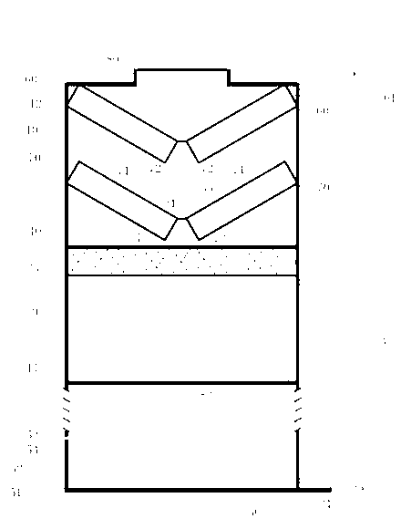
[0024] figure 1 It is a schematic diagram of the main structure and working principle of the evaporative condenser and its heat source device as the first specific embodiment of the present invention. The evaporative condenser and its heat source device of the present invention mainly include a box body 10 divided into upper and lower sections, which are connected together by a frame 12 to form a whole, and the first heat exchanger 20 is arranged at the lower section of the box body 10 The upper part, the bottom of the lower section of the box body 10 is a water collection tank 50, and an inlet grille 11 is provided between the water collection box 50 and the first heat exchanger 20, and the inside of the upper secti...


PUM


Abstract

The invention relates to an evaporative-type condenser and a heat source device of the evaporative-type condenser. The evaporative-type condenser and the heat source device of the evaporative-type condenser comprise an upper segment box body, a lower segment box body, an air inlet and an air outlet, wherein a water-collecting box is arranged at the bottom of the lower segment box body, a first heat exchanger and a cooling water spray device are arranged inside the box body. A second heat exchanger (heat source exchanger) is arranged inside the upper segment box body, a water-blocking plate is arranged on the lower portion of the second heat exchanger, an outlet of the second heat exchanger is in series connection with an inlet of the first heat exchanger through a pipeline, and a draught fan is arranged on the top of the upper segment box body and is tightly connected with the air outlet. In addition, valves are arranged on an inlet pipeline of the first heat exchanger and an outlet pipeline and an inlet pipeline of the second heat exchanger and adjust and control working states of the first heat exchanger and the second heat exchanger through opening and closing of the valves, and accordingly a system smoothly operates in summer when the evaporative-type condenser and the heat source device of the evaporative-type condenser are used as a condenser, and can provide a sufficient heat source to the system when being used as an evaporator in winter.

Description

technical field [0001] The invention relates to the cold and heat source technology in the heat pump air conditioning system, in particular to an evaporative condenser and its heat source device, which solves the problem that the evaporative condenser cannot provide sufficient heat source for the system as an evaporator in winter, It solves the problem that the condensing pressure of the evaporative condenser is too high under hot and humid environment conditions in summer. Background technique [0002] In the heating and cooling dual-purpose heat pump air conditioning system, the cold and heat sources are usually ground source and air source. The ground source heat pump air conditioner uses a water-cooled heat exchanger, and the air source heat pump air conditioner uses an air-cooled heat exchanger. Ground source heat pump air conditioners are divided into two types: water source heat pump air conditioners and ground temperature heat pump air conditioners. Water source heat...

Claims


Application Information

Patent Timeline
IPC IPC(8): F25B39/04F25B39/02
Inventor 刘玉岭黄文斐刘方然
Owner 刘玉岭
Why Eureka
Try Eureka