
Automatic opposite-angle clamping type omnidirectional rotary cantilever support

A cantilever bracket and clamping technology, applied in the direction of machine/bracket, supporting machine, mechanical equipment, etc., can solve the problems of unable to clamp, unable to realize all-round rotation in space, inconvenient to move, etc., to achieve the effect of easy clamping

Inactive Publication Date: 2013-05-22
UNIV OF SHANGHAI FOR SCI & TECH
View PDF5 Cites 13 Cited by
  • Summary
  • Abstract
  • Description
  • Claims
  • Application Information

AI Technical Summary

Problems solved by technology

[0004] 1) Part of the bracket adopts a long-arm structure, which can expand and contract in one direction, so as to adjust the distance from the person to the portable device, but cannot realize all-round rotation in space
[0005] 2) The clamping structure of the mobile device can only clamp one type of mobile device, and cannot clamp mobile devices of different sizes and shapes
[0006] 3) The rotating fixed structure adopts threaded connection. For the handicapped and the elderly with weak hands, it cannot be effectively tightened to achieve the fixing effect
[0007] 4) Part of the support is floor-standing, the chassis is large and heavy, and it is inconvenient to move

Method used


Image

  • Automatic opposite-angle clamping type omnidirectional rotary cantilever support
  • Automatic opposite-angle clamping type omnidirectional rotary cantilever support
  • Automatic opposite-angle clamping type omnidirectional rotary cantilever support

Examples


Embodiment Construction

[0021] The present invention will be further described below in conjunction with the accompanying drawings and embodiments.

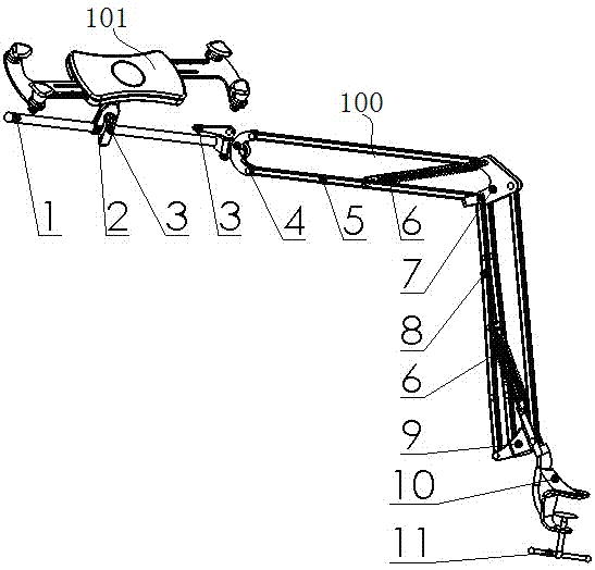
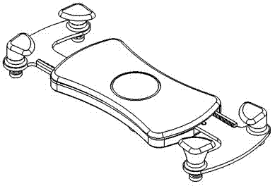
[0022] Such as figure 1 As shown, the automatic diagonal clamping omnidirectional rotating cantilever support of the present invention is composed of a universal support 100 and a clamping device 101 .

[0023] The universal bracket 100 includes a rotating rod 1, a universal clip 2, a clamping turnbuckle 3, a third link 4, a second support rod 5, a gravity balance spring 6, a second link 7, a first support rod 8, a first Link 9, fixed fixture 10, fixed rotary handle 11.

[0024] The upper and lower ends of the second link 7 are movably linked with the third link 4 and the first link 9 through the second support rod 5 and the first support rod 8 respectively, forming a four-bar linkage structure of the upper and lower arms, and the second link Between the part 7 and the second support bar 5 and between the first link 9 and the first support bar 8, a gr...


PUM


Abstract

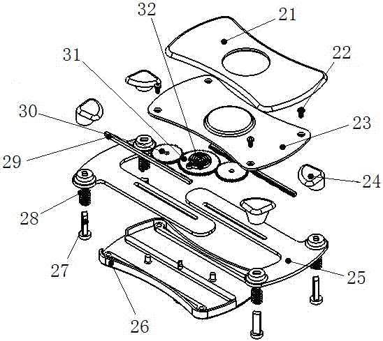
The invention relates to an automatic opposite-angle clamping type omnidirectional rotary cantilever support which is composed of a universal support and a clamping device. The upper end and the lower end of a second chaining piece in the universal support are respectively and movably connected with a third chaining piece and a first chaining piece in a chaining mode through a second supporting rod and a first supporting rod so as to form an upper and lower arm four-connecting-rod structure. Gravitational equilibrium springs are respectively arranged between the second chaining piece and the second supporting rod and between the first chaining piece and the first supporting rod. The lower end of the first chaining piece is connected with a fixed clamp in a rotating mode, a fixed screwing handle is arranged in the fixed clamp, the front end of the third chaining piece is hinged with a rotary rod, a clamping screwing buckle is arranged on a hinged portion, and the rotary rod is connected with the clamping device through a universal clamping piece and the clamping screwing buckle. A holding strip is arranged in an outer shell of the clamping device, a rack is arranged on the holding strip, the rack is meshed with a pinion, the pinion is meshed with a gear wheel, the pinion and the gear wheel are connected on a protruded shaft of the outer shell, the center of a torsion spring is fixed on the protruded shaft of the outer shell, and the other end of the torsion spring is fixed on a protruded shaft of the gear wheel, and a clamping head is arranged at the front end of the holding strip.

Description

technical field [0001] The invention relates to a mobile portable device support for the elderly and disabled, especially suitable for clamping tablet computers, mobile phones and other devices, and is convenient for reading without hands when lying down. Background technique [0002] For the increasingly large number of elderly and disabled people, in addition to ensuring their normal material life, it is also necessary to meet their spiritual, psychological and cultural needs. , In the information age with the rapid development of technology and the Internet, they are eager to contact and understand the world with the help of portable devices and the Internet, and at the same time communicate with others conveniently. [0003] There are also mounts on the market for holding mobile portable devices such as tablets, mobile phones, etc. Although its structure can realize omni-directional rotation, it is not specially designed for the elderly and the disabled. Therefore, if ...

Claims


Application Information

Patent Timeline
Patent Type & Authority Applications(China)
IPC IPC(8): F16M13/02F16M11/12F16M11/18
Inventor 喻洪流王吴东余俊瑶付宏远
Owner UNIV OF SHANGHAI FOR SCI & TECH
Learn More