Eureka AIR delivers breakthrough ideas for toughest innovation challenges, trusted by R&D personnel around the world.

Flat resistance fiber air pipe and train using the same

An air duct and fiber technology, which is applied in the field of anti-slack fiber air ducts and the trains in which they are applied, can solve the problems of complex structure of air supply air ducts, unfavorable high-speed safe operation, and heavy material of air supply air ducts, etc. Convenience, lowering the center of gravity of the vehicle, and uniform air velocity

Inactive Publication Date: 2013-05-22
CHANGZHOU UNIV
View PDF5 Cites 0 Cited by
  • Summary
  • Abstract
  • Description
  • Claims
  • Application Information

AI Technical Summary

Problems solved by technology

[0004] The technical problem to be solved by the present invention is: in order to solve the problem that the material of the air supply duct used by the existing train is relatively heavy, resulting in a high center of gravity of the train, which is not conducive to high-speed safe operation, the structure of the air supply duct is complicated, the production cost is high, and the There are problems such as blowing sensation, and because the fiber cloth air duct, which has the advantages of light weight, easy cleaning, large air supply area, low flow rate, and strong human comfort, is easy to collapse when the air supply is stopped, hindering its application in trains problem, the present invention provides an anti-shrinkage fiber air duct and its applied train to solve the above problems

Method used


Image

  • Flat resistance fiber air pipe and train using the same
  • Flat resistance fiber air pipe and train using the same
  • Flat resistance fiber air pipe and train using the same

Examples


Embodiment Construction

[0018] The present invention is described in further detail now in conjunction with accompanying drawing. These drawings are all simplified schematic diagrams, which only illustrate the basic structure of the present invention in a schematic manner, so they only show the configurations related to the present invention.

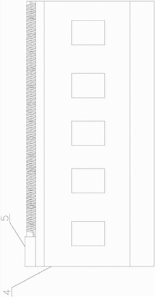
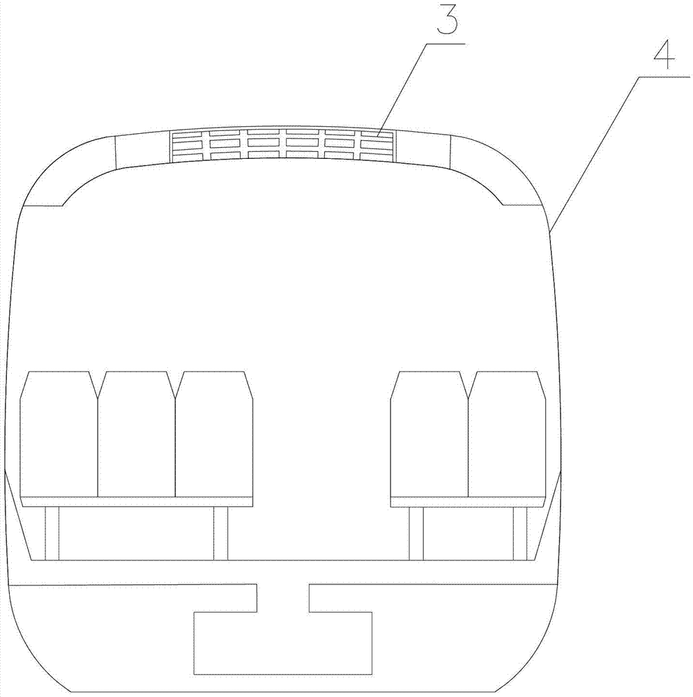
[0019] Such as figure 1 As shown, the present invention provides an anti-collapsing fiber air duct, including an air duct main body 1 made of a flame-retardant material, and a fiber micro-duct 2 for supporting the air duct main body 1 from the inside is arranged inside the air duct main body 1, The fiber micro-duct 2 is a sealed elongated duct. The fiber micro-duct 2 is made of airtight fiber material and filled with air.

[0020] One end of the fiber micro-pipe 2 has an opening for filling and discharging air and a plug to close the opening, then the fiber micro-pipe 2 will dry up due to unfilled gas, which is convenient for construction and carrying. The f...


PUM


Abstract

The invention provides a flat resistance fiber air pipe which comprises an air pipe main body made of flame-retardant materials. A fiber micro pipeline used for supporting the air pipe main body from the inner portion is arranged inside the air pipe main body. The fiber micro pipeline is a sealed long-striped pipeline and is made of airtight fiber materials and filled with air. The fiber micro pipeline is curled and fixed inside the air pipe main body in a spiral shape. The flat resistance fiber air pipe can effectively prevent an easily-flat phenomenon after operation of a ventilating system is stopped. Meanwhile, according to a train applying the flat resistance fiber air pipe, due to the fact that quality of the upper portion of a train body is lightened, the gravity center of the train body is enabled to be lowered, and safety during high-speed running of the train is improved. In addition, the flat resistance fiber air pipe is large in air-out area and even in air-out speed, a passenger is enabled to have no local draught sensation, comfortable sensation is enabled to be strong, secondary pollution of air inside a carriage can be effectively reduced, and therefore a comfortable, healthy, clean and sanitary riding environment is provided for the passenger.

Description

technical field [0001] The invention relates to a fiber cloth air duct and a train using the same, in particular to an anti-shrink fiber air duct and a train using the same. Background technique [0002] At present, there are disadvantages such as uneven distribution of air temperature and speed along the height and length of the carriage in the train carriage, a feeling of blowing in some areas, and poor comfort for personnel. In order to improve this situation, baffles with specific angles and heights usually need to be arranged inside the air-conditioning air duct. This makes the train air supply air duct complex in structure, high in production cost, and heavy in quality, and the heavier air supply system will make the center of gravity of the train higher, which is not conducive to the high-speed safe operation of the train. In addition, after the system has been in operation for a long time, due to limited space, difficult cleaning or high cleaning costs, a large amou...

Claims


Application Information

Patent Timeline
IPC IPC(8): B61D27/00
Inventor 陈孚江王小兵邱伶艳王树立
Owner CHANGZHOU UNIV
Why Eureka
Eureka Blog
Learn More