
Reactive compensation differentiation collocation method of 10kV distribution lines

A technology of distribution lines and configuration methods, applied in the directions of reactive power compensation, reactive power adjustment/elimination/compensation, etc., which can solve problems such as heavy calculation workload, inability to guarantee the accuracy and simultaneity of load measurement, and lack of classification standards

Inactive Publication Date: 2015-03-11
SOUTH CHINA UNIV OF TECH
View PDF3 Cites 0 Cited by
  • Summary
  • Abstract
  • Description
  • Claims
  • Application Information

AI Technical Summary

Problems solved by technology

Given planning suggestions through traditional reactive power optimization, the value requirements of each characteristic parameter need to be specified, and different calculation processes are required for different planning subjects. Factors such as distributed power sources and special lines have a great impact on the planning results, and the calculation workload Big
[0009] ③ Lack of classification standards
[0010] In general, how to reasonably select the reactive power compensation point and determine the compensation capacity, effectively maintain the voltage level of the system and improve the voltage stability of the system, and avoid the long-distance transmission of a large amount of reactive power, etc., at present, Many power units mainly rely on the experience of planners for reactive power planning, which cannot meet the actual situation of the distribution network, and the effect of reactive power compensation is not good, making it difficult to maximize the benefits of limited funds
In addition, the accuracy and simultaneity of load measurement on distribution network lines cannot be guaranteed at this stage, and the technical level of maintenance personnel is uneven. This situation brings certain difficulties to the calculation of reactive power compensation in distribution network

Method used


Image

  • Reactive compensation differentiation collocation method of 10kV distribution lines
  • Reactive compensation differentiation collocation method of 10kV distribution lines
  • Reactive compensation differentiation collocation method of 10kV distribution lines

Examples


Embodiment Construction

[0084] The following is an example for the 10kV Liyuba Line of Shaoguan Matou Station of Guangdong Power Grid. The power supply area of ​​the substation is mainly for rural loads, and a small part of industrial loads, and small hydropower connected to the grid.

[0085] combine figure 1 The planning process, the differential configuration method of reactive power compensation for 10kV distribution lines includes the following steps:

[0086] (1) The 10kV Liyuba Line of Shaoguan Matou Station of Guangdong Power Grid is divided into mountainous source-containing lines according to its electrical characteristics;

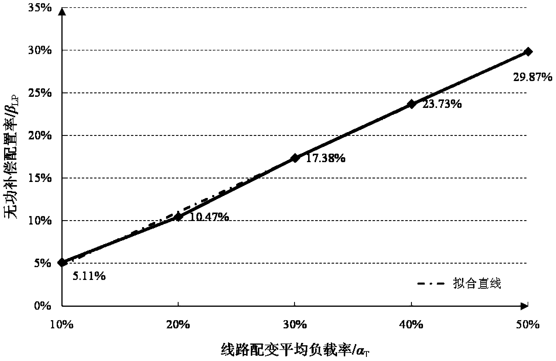
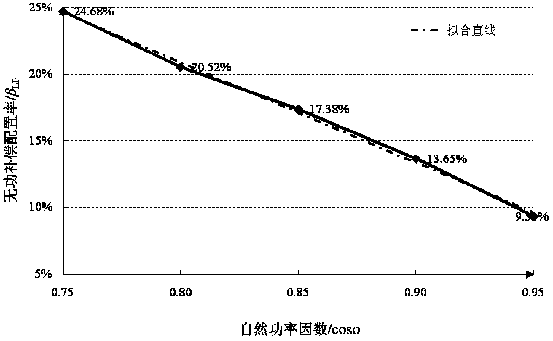
[0087] (2) Determine the base state value of the characteristic parameters of the 10kV Liyuba Line at the Matou Station in Shaoguan, Guangdong Power Grid, as shown in Table 1; establish the base state model of the 10kV Liyuba Line at the Matou Station in Shaoguan, and the specific electrical parameters are shown in Table 2;

[0088] Table 1 The ground state parameter...


PUM


Abstract

The invention provides a reactive compensation differentiation collocation method of 10kV distribution lines. Firstly the 10kV distribution lines of a power grid are classified, and ground state models are constructed according to characteristic parameters of each kind of lines; then sensitivity between the characteristic parameters of the lines and a reactive compensation optimized collocation rate under the ground state models of each kind of the lines is calculated, reactive compensation collocation recommendation range tables under two-dimensional or multi-dimensional changes of the characteristic parameters of the lines are calculated, and a reactive compensation collocation rate recommendation mid-value general table of the lines is formed; and eventually according to the reactive compensation collocation rate recommendation mid-value general table of the lines, the optimized reactive compensation collocation for the 10kV distribution lines is guided. The reactive compensation differentiation collocation method of the 10kV distribution lines avoids problems of solution complication of a sensitivity coefficient and large calculated amount, and can visually and effectively confirm the reactive compensation collocation of similar distribution lines.

Description

technical field [0001] The invention relates to a reactive power compensation capacity configuration planning technology of a low-voltage distribution network, in particular to a differential configuration method for reactive power compensation of a 10kV distribution line. Background technique [0002] Reactive power compensation in distribution network is one of the effective means to improve voltage quality, reduce loss and save energy. The task of distribution network reactive power planning is to determine the way of reactive power compensation, select the appropriate reactive power compensation device, and reasonably determine the reactive power load distribution on the basis of the determined grid structure. The position of power compensation point, reactive power compensation capacity and group number and other relevant information can ensure that the distribution network can supply power to users safely, high-quality and economically. [0003] Distribution network r...

Claims


Application Information

Patent Timeline
IPC IPC(8): H02J3/18
CPCY02E40/30
Inventor 张勇军彭思华李钦豪
Owner SOUTH CHINA UNIV OF TECH
Learn More