Visualization laser receiver

A laser receiver and laser technology, applied in the direction of instruments, measuring instruments, measuring devices, etc., can solve the problems of poor accuracy, slow positioning, and easy to be restricted by the site, and achieve the effect of good accuracy and fast positioning

Inactive Publication Date: 2013-05-15
NANJING CHERVON IND
View PDF5 Cites 1 Cited by
  • Summary
  • Abstract
  • Description
  • Claims
  • Application Information

AI Technical Summary

Problems solved by technology

[0005] The existing laser receivers are unintuitive in use, slow in positioning, poor in accuracy, and easily restricted by the site

Method used


Image

  • Visualization laser receiver
  • Visualization laser receiver
  • Visualization laser receiver

Examples


Embodiment Construction

[0022] The present invention will be specifically introduced below in conjunction with the accompanying drawings and specific embodiments.

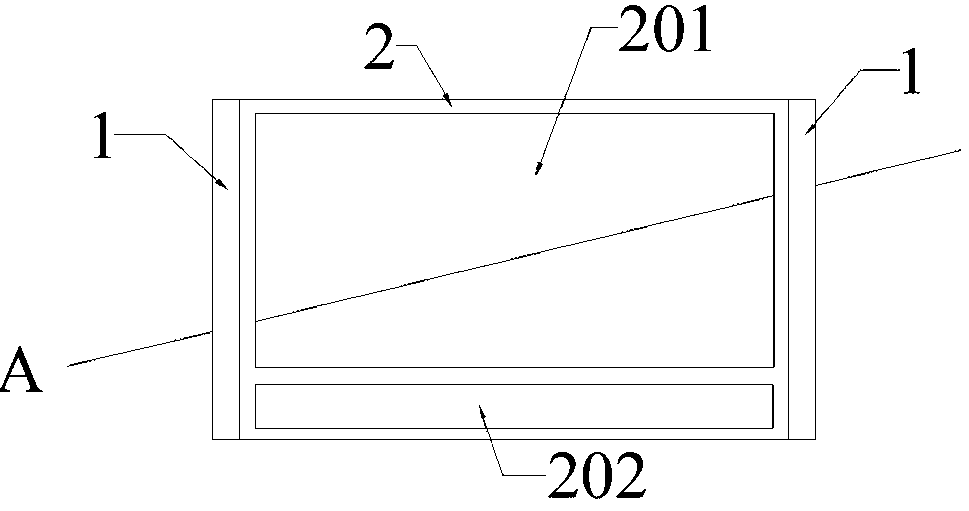
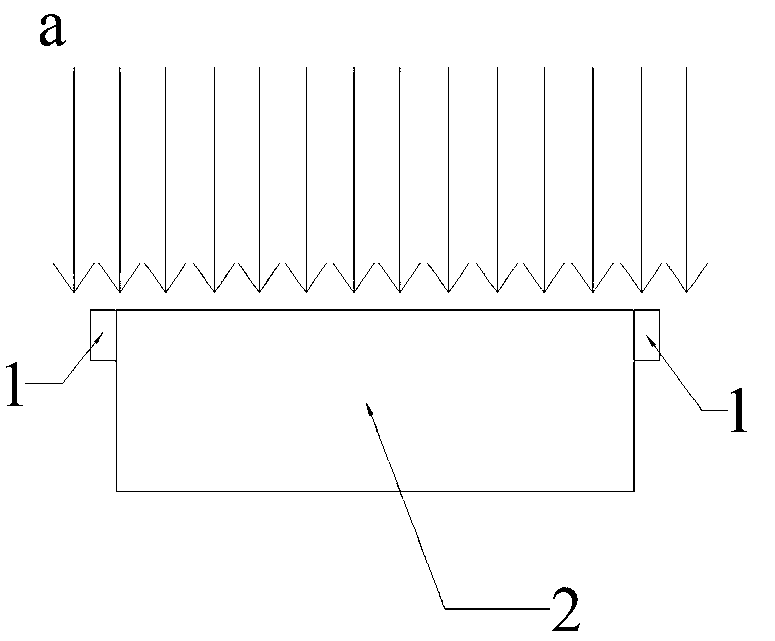
[0023] refer to Figure 1 to Figure 4 As shown, the visual laser receiver of the present invention includes: more than one photosensitive array 1 , a controller, and a visual interface 2 . The controller drives the photosensitive array 1 and receives its feedback signal, and the visual interface 2 simulates the measured laser with a visible pattern under the control of the controller; the controller forms an electrical connection with the visual interface 2 and the photosensitive array 1 .

[0024] The photosensitive array 1 includes a plurality of photosensitive units, and these photosensitive units may be photoelectric elements such as CCD chips, CMOS chips, or PSD chips (Position Sensitive Detector, position sensitive device). The visual interface 2 refers to a human-computer interaction interface capable of providing visual images to...


PUM


Abstract

The invention discloses a visualization laser receiver. The visualization laser receiver comprises more than one group of sensitization arrays for detecting laser, a controller and a visualization interface, wherein the controller is used for driving the sensitization arrays and can receive a feedback signal, and the visualization interface is controlled by the controller so as to simulate the detected laser in a visual pattern; and the controller and the visualization interface and the sensitization arrays can form electric connection. The visualization laser receiver provided by the invention has the advantages that the position of a lasing surface can be visually reacted, the localization is rapid, the precision is good, and the visualization laser receiver is not limited by a field.

Description

technical field [0001] The invention belongs to the field of laser measurement and control devices, and in particular relates to a visual laser receiver. Background technique [0002] When laser marking or sweeping products are used for marking work, one or more laser surfaces are often issued as a reference. [0003] In accordance with the relevant safety regulations, in engineering measurement, the power of the laser used for marking lines is limited, because if the power of the laser is too high, it will cause damage to human eyes and other organs. Just like this, the brightness of the laser is also limited when it is used for marking lines, which makes it difficult to observe the above-mentioned laser surface with the naked eye at a long distance. [0004] In order to solve this problem, a laser receiver is often used at the receiving position. The existing laser receiver usually uses two upper and lower photoelectric panels. By comparing the difference in luminous flux...

Claims


Application Information

Patent Timeline
Patent Type & Authority Applications(China)
IPC IPC(8): G01C15/00G01C15/14
Inventor 陈明周其伟
Owner NANJING CHERVON IND
Why Eureka
Try Eureka