Thermostatic handle used for thermostatic valve

A thermostatic valve and handle technology, applied in the field of thermostatic handles, can solve problems such as inaccurate temperature of thermostatic valves, and achieve the effect of avoiding inaccurate temperature control and improving accuracy

Inactive Publication Date: 2013-05-15
BEIJING JINGHUA YUCHUANG ENERGY SAVING EQUIP
View PDF7 Cites 1 Cited by
  • Summary
  • Abstract
  • Description
  • Claims
  • Application Information

AI Technical Summary

Problems solved by technology

[0005] Furthermore, the existing technology uses the self-locking function of the thread of the heart and the thread of the temperature package ferrule, and then adjusts to the required temperature. If a child adjusts or something hits it, the thermostat handle will rotate and affect the temperature of the thermostat valve.

Method used


Image

  • Thermostatic handle used for thermostatic valve
  • Thermostatic handle used for thermostatic valve
  • Thermostatic handle used for thermostatic valve

Examples


Embodiment Construction

[0034] The core of the present invention is to provide a thermostatic handle for a thermostatic valve. The structural design of the thermostatic handle can avoid the inversion phenomenon after the thread self-locking fails and the problem of inaccurate temperature control caused by children's artificial rotation, thereby improving the The accuracy of temperature control; in addition, it also avoids the set temperature being too high or too low, resulting in energy waste or frost.

[0035] In order to make those skilled in the art better understand the technical solutions of the present invention, the present invention will be further described in detail below with reference to the accompanying drawings and specific embodiments.

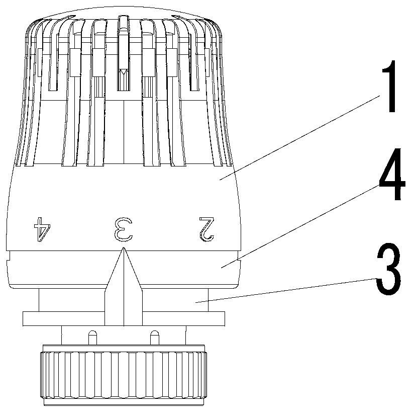
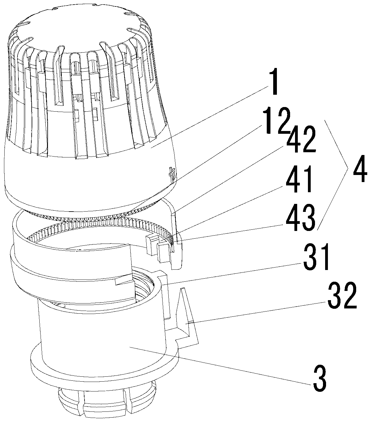
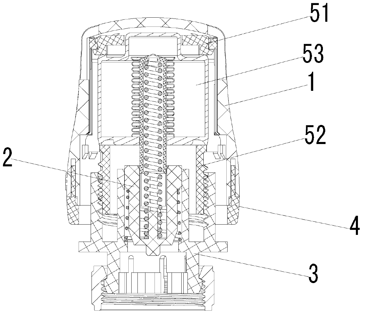
[0036] Please refer to figure 1 , figure 2 and image 3 , figure 1 is an axonometric view of a thermostatic handle in an embodiment of the present invention; figure 2 for figure 1 Schematic diagram of the cooperation of the middle thermostatic ...


PUM


Abstract

The invention discloses a thermostatic handle used for a thermostatic valve. A limiting ring (4) is arranged between a handle outer shell (1) and a heart body (3) of the thermostatic handle, the lower end of the handle outer shell (1) is capable of breaking away from the upper portion of the limiting ring (4) in the axial direction, so that the handle outer shell (1) and the limiting ring (4) are capable of changing the relative position in the circumferential direction conveniently and then getting close and being fixed in the axial direction, and the limiting ring (4) is movably sleeved outside the circumference of the heart body (3). Between the inner wall of the lower portion of the limiting ring (4) and the outer wall of the circumference of the heart body (3), one is provided with a limiting groove (41), the other is provided with a limiting baffle block (31) capable of being arranged in the limiting groove (41), and the limiting groove (41) and the limiting baffle block (31) are capable of being separated along the axial direction of the limiting ring (4). Through the structural design of the thermostatic handle, the problems of a reverse rotation phenomenon caused by failure of thread self-locking and inaccurate temperature control caused by manual rotation by a child can be avoided, and therefore accuracy of temperature control is improved. In addition, energy waste or frost due to the fact that the set temperature is too high or too low is avoided.

Description

technical field [0001] The invention relates to the technical field of thermostatic valves, in particular to a thermostatic handle for thermostatic valves. Background technique [0002] The thermostatic valve is the temperature-sensing component in the radiator system. When working, the hot water enters the water inlet in the valve body assembly. When the temperature in the environment is too high or too low, the temperature sensing element of the thermostatic handle automatically extends and shortens to push the valve core rod to close the valve port or adjust the valve port flow. size, thereby controlling the temperature in the environment. If you need to change the temperature in the environment, you can turn the thermostatic handle to align the scale with the arrow in the valve body connector to reach the desired temperature. [0003] In the prior art, when the thread of the heart body is matched with the thread of the temperature bulb ferrule, since the temperature of...

Claims


Application Information

Patent Timeline
IPC IPC(8): F16K31/60F16K31/68F16K35/00
Inventor 陈杰聪
Owner BEIJING JINGHUA YUCHUANG ENERGY SAVING EQUIP
Why Eureka
Try Eureka