
Thermosensitive control variable pitch fan

A fan and heat-sensitive technology, applied in the field of heat-sensitive control variable-pitch fans, can solve the problem of not being able to change the air intake of the fan

Inactive Publication Date: 2013-05-15
李青青
View PDF0 Cites 0 Cited by
  • Summary
  • Abstract
  • Description
  • Claims
  • Application Information

AI Technical Summary

Problems solved by technology

[0002] At present, ordinary engine fans are all mechanical or direct-connected devices, and the air intake of the fan cannot be changed with the temperature of the engine.

Method used


Image

  • Thermosensitive control variable pitch fan

Examples


Embodiment Construction

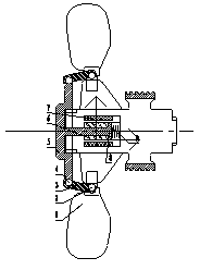
[0010] Below in conjunction with Fig. 1, describe in detail the concrete work situation that the present invention proposes, figure 1 The fan blade (1) and the tie rod (3) are connected through the fan blade ball head (2), the tie rod (3) is connected with the distance change disc (5) through the distance change disc ball head (4), and the piston (8) and the variable The distance plate (5) is fixedly connected, and the expansion wax (6) is housed in the heat conduction ring (7), and the balance spring (9) is connected with the piston (8).

[0011] The temperature change is transferred to the expansion wax (6) through the heat conduction ring (7), and the expansion wax (6) is transformed into different volume changes corresponding to different temperature changes, and pushes the piston (8) to drive the variable distance disc ( 5) Pull the rod (3) to the fan blade (1), thereby changing the pitch of the fan blade (1), so that it can obtain different air intake volumes at the same...


PUM


Abstract

The invention relates to a thermosensitive control variable pitch fan. Change of heat conduction expansion wax on temperature is correspondingly converted into volume change to push a piston to driven a variable pitch disk connected with the piston, a pull rod and a fan blade, then blade pitch of the fan blade can be changed to achieve different air inlet amounts under the same rotation speed, and accordingly the purpose of direct-distance air cooling accurate temperature control of an engine can be well achieved.

Description

technical field [0001] The present invention is a heat-sensitive control variable-pitch fan in the field of electromechanical technology. Through heat conduction, the wax expands to correspondingly transform different temperature changes into different volume changes, and pushes the piston to drive the fan blades, thereby changing the pitch of the fan blades. In order to obtain different air intake volumes at the same speed, the purpose of precise temperature control of the direct air cooling of the engine can be achieved. Background technique [0002] At present, ordinary engine fans are all mechanical or direct-connected devices, and the air intake of the fan cannot be changed with the temperature of the engine. Contents of the invention [0003] The object of the present invention is to provide a heat-sensitive control variable-pitch fan to realize the precise temperature control of engine variable-pitch air cooling. [0004] Its purpose is to achieve this, figure 1 I...

Claims


Application Information

Patent Timeline
IPC IPC(8): F04D27/00
Inventor 李青青
Owner 李青青
Learn More