
Vertical type suspension structure wind driven generator

A technology of wind turbines and suspension structures, which is applied in the direction of wind turbine components, wind engines, and wind motor combinations. sexual effect

Inactive Publication Date: 2013-05-15
丁万平
View PDF6 Cites 1 Cited by
  • Summary
  • Abstract
  • Description
  • Claims
  • Application Information

AI Technical Summary

Problems solved by technology

[0002] Wind power generation is an inexhaustible green energy. With its strong future development momentum, it is valued and strongly developed by contemporary society. In the existing technology, wind power generation is mostly electric fan structure. The entire power generation equipment, Together with the fan, it should be erected to a height of more than 100 meters through the fan pole, thus forming an electric fan wind turbine. 1. The generator and gearbox of the entire wind turbine should be set on the pole, 2. Stand alone The pole requires high strength, the foundation requires deep and strong, 3. It needs windward steering equipment, 4. The structure is complex and organized, and maintenance is extremely inconvenient

Method used


Image

  • Vertical type suspension structure wind driven generator
  • Vertical type suspension structure wind driven generator
  • Vertical type suspension structure wind driven generator

Examples


Embodiment Construction

[0014] The technical solutions and embodiments of the present invention will be further described below in conjunction with the accompanying drawings.

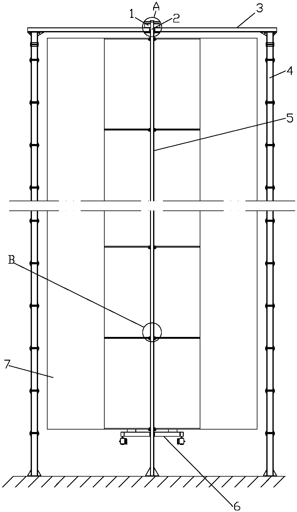
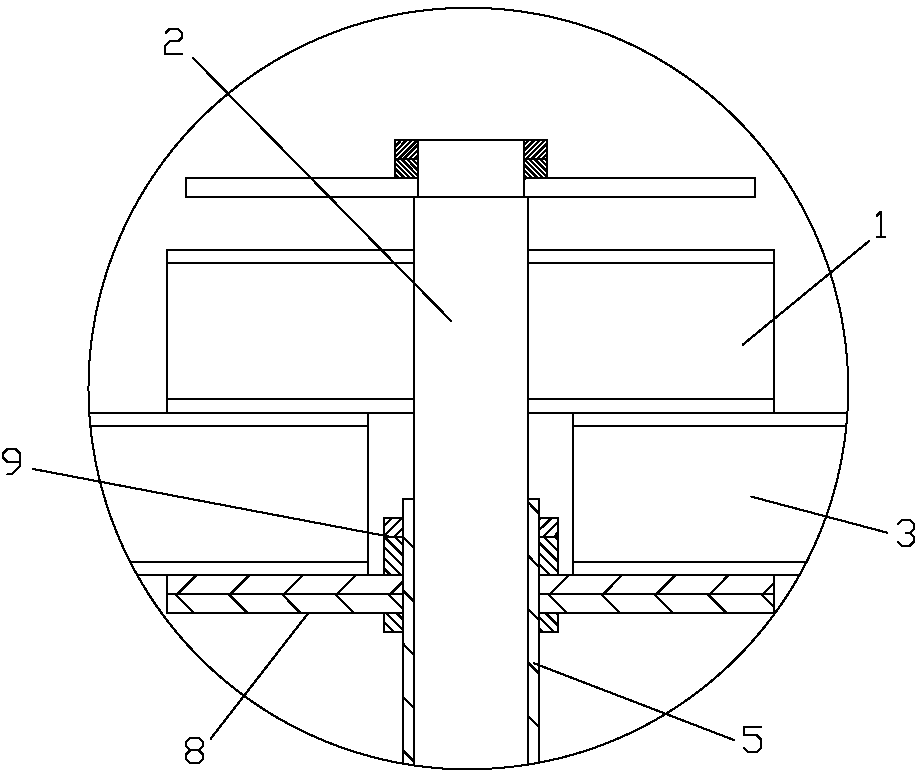
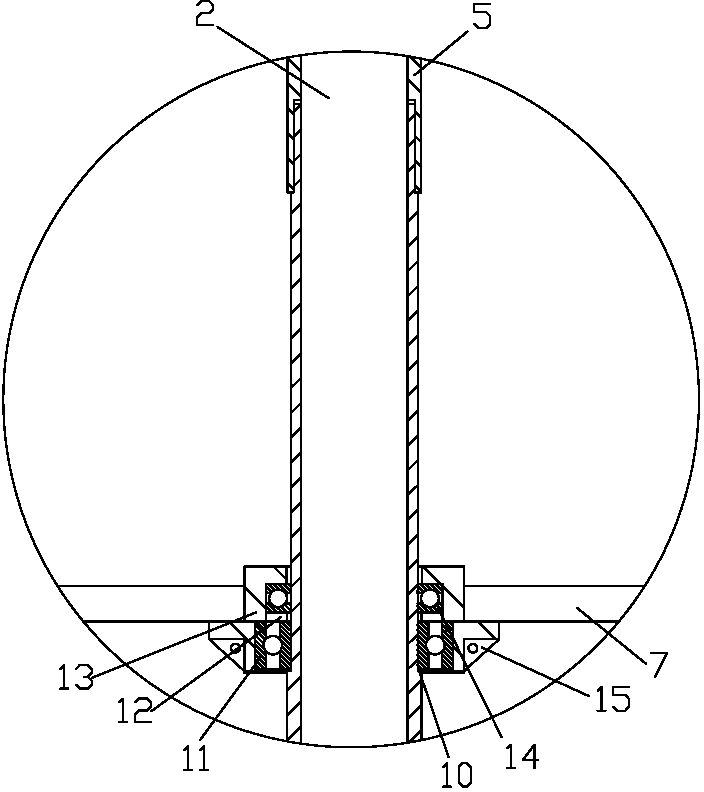
[0015] As shown in the figure, the wind power generator with vertical suspension structure involved in the present invention includes a wind-driven device and a power generation device, including a suspension column, a suspension beam, a bearing seat, a center column and a center column cover, and the four suspension columns 4 Evenly and vertically distributed around, the tops of the suspension columns 4 are fixedly connected with the suspension beams 3 respectively, the upper middle of the suspension beams 3 is provided with a central shaft seat 1, and the upper end of the center column 2 is mounted in the center shaft seat 1 , the center column cover 5 is set on the outside of the center column 2, and the upper end of the center column cover 5 is fixed on the suspension beam 3, and the center column cover 5 is formed by sever...


PUM


Abstract

The invention relates to a vertical type suspension structure wind driven generator which comprises pneumatic devices, a power generation device, a suspension stand column, a suspension cross beam, bearing seats, a central stand column and a central stand column sleeve, wherein the top end of the suspension stand column is fixedly connected with the suspension cross beam, the central stand column is arranged on the outer side of the central stand column in a sleeved mode, the upper end of the central stand column sleeve is fixed on the suspension cross beam, a seam allowance is arranged on each section of the central stand column sleeve, multiple bearing seats are respectively arranged on the corresponding central stand column sleeve in a sleeved mode, and the lower end faces of bearings arranged in the bearing seats are pressed on the corresponding seam allowance. The pneumatic devices are arranged on the multiple bearing seats, and a power generator is connected with the pneumatic devices. By the technical scheme, tower type design is changed into hanging clock type design, so that bearing capacity of a whole wind driven generator is greatly improved, and the vertical type wind driven generator with the height of dozens of meters or even more can be manufactured. The vertical type suspension structure wind driven generator is simple in structure, and quite convenient to install and maintain, and greatly reduces manufacturing and maintenance cost.

Description

technical field [0001] The invention relates to a wind power generator, in particular to a wind power generator with a vertical suspension structure. Background technique [0002] Wind power generation is an inexhaustible green energy. With its strong future development momentum, it is valued and strongly developed by contemporary society. In the existing technology, wind power generation is mostly electric fan structure. The entire power generation equipment, Together with the fan, it should be erected to a height of more than 100 meters through the fan pole, thus forming an electric fan wind turbine. 1. The generator and gearbox of the entire wind turbine should be set on the pole, 2. Stand alone The pole requires high strength, and the foundation needs to be deep and firm. 3. Windward steering equipment is required. 4. The structure is complex and organized, and maintenance is extremely inconvenient. Contents of the invention [0003] In view of this, the technical pro...

Claims


Application Information

Patent Timeline
Patent Type & Authority Applications(China)
IPC IPC(8): F03D9/00F03D11/00
CPCY02E10/722Y02E10/72Y02P70/50
Inventor 丁万平李士英
Owner 丁万平
Learn More