High-power motorboat outboard engine flywheel

A technology for motorboats and outboard motors, which is applied in the directions of flywheels, ignition generator rotors, etc., can solve the problems of complicated installation of the triggering magnetic ring or magnetic sheet, the overall size of the shaft sleeve combination is increased, and the effective triggering energy is reduced. The effect of power generation and triggering energy, increasing aesthetics and saving resources

Inactive Publication Date: 2013-05-15
CHONGQING UNIV OF TECH
View PDF7 Cites 2 Cited by
  • Summary
  • Abstract
  • Description
  • Claims
  • Application Information

AI Technical Summary

Problems solved by technology

The installation of the inner trigger magnetic ring or magnetic sheet is more complicated. Usually, a magnetic isolation ring is used to cover the magnetic ring or magnetic sheet on the shaft sleeve assembly. This method has a more complicated structure. When installing, the magnetic ring or magnetic sheet is covered inside. The installation operation is cumbersome and complicated. The magnetic ring or magnetic sheet is cove

Method used


Image

  • High-power motorboat outboard engine flywheel
  • High-power motorboat outboard engine flywheel
  • High-power motorboat outboard engine flywheel

Examples


Embodiment Construction

[0028] The present invention will be described in further detail below in conjunction with the accompanying drawings and specific embodiments.

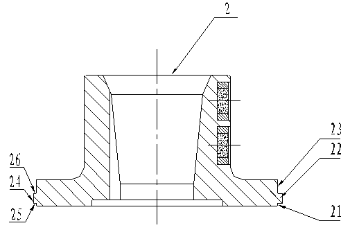
[0029] Such as figure 2 , 3 , 4, 5, 6, 7, and 8, the flywheel of the high-power motorboat outboard motor of the present invention includes a flywheel body 1, and the flywheel body 1 mainly includes a shaft sleeve assembly 2, a cylinder body 3, a magnetic tile 4 and an inner Trigger the magnetic piece 6, the flywheel body 1 is a ring-shaped structure, the bushing combination 2 located on the inner side is connected with the cylinder body 3, the bushing combination 2 is set in the center hole of the cylinder body 3; the magnetic tile 4 is set in the cylinder body 3 and the magnetic tile inner cover 5, the magnetic tile 4 and the magnetic tile inner cover 5 are connected to the cylinder body 3 through glue, buckle edges, etc., or are arranged on the cylinder body 3 through the support ring 14, and the magnetic tile 4 is along the cylin...


PUM


Abstract

The invention discloses a high-power motorboat outboard engine flywheel. An outer circumference face, matched with an inner hole of a cylinder body, of a shaft sleeve is arranged to be in a step structure and is composed of an outer layer disc, an outer edge boss and an inner layer disc, wherein the an outer layer disc, the outer edge boss and the inner layer disc are arranged in sequence, the diameter of the outer edge boss is larger than the diameter of the outer layer disc and the diameter of the inner layer disc, and a plurality of sections of cutting string grooves are formed in the outer circumference face of the outer edge boss. When the high-power motorboat outboard engine flywheel is assembled, the outer layer disc of the shaft sleeve is placed in a step small hole of the cylinder body. A plurality of sections of gaps are formed on the corresponding portions of the cutting string grooves of the outer edge boss and a large hole of the cylinder body. A die is composed of an upper die and a lower die which are arranged in a matched mode. An upper convex die is arranged on the upper die, and a lower convex die is arranged on the lower die. The shaft sleeve and the cylinder body are connected into a whole through an upper baffle block, a lower baffle block and a rotation-stopping baffle block, wherein the upper baffle block and the lower baffle block are formed on the outer edge boss. According to the connecting method, a die stamping method is adopted, the shaft sleeve and the cylinder body are firmly connected into the whole, the size of the shaft sleeve is obviously decreased, consumed materials of the shaft sleeve are reduced, and precious resources and machining work hours are saved.

Description

technical field [0001] The invention relates to a flywheel of a motorboat power device, in particular to a flywheel of a high-power motorboat outboard motor. Background technique [0002] The flywheel of the high-power motorboat outboard motor in the prior art is a ring-shaped structure, mainly including a cylinder body, an inner cover, a magnetic tile arranged between the cylinder body and the inner cover, and a shaft sleeve combination integrally connected with the cylinder body , the shaft sleeve assembly is located inside the flywheel, the inner cover is usually a thin sheet ring made of stainless steel, and the magnetic tiles are 4 pieces, 6 pieces, 8 pieces, etc. arranged evenly along the circumference of the inner wall of the cylinder, and are connected with the power device of the outboard motor. Adapt to the working conditions, rely on the support and positioning of the magnetic tile fixing frame. For high-grade large-displacement magnetic motor flywheel rotors, fo...

Claims


Application Information

Patent Timeline
IPC IPC(8): F02P1/02F16F15/30
Inventor 甘树德杜长华杨自为甘贵生许惠斌陈方贾镜杨
Owner CHONGQING UNIV OF TECH
Why Eureka
Try Eureka