
Automated assembly method of microswitch shrapnel and carrying-out device thereof

A micro-switch, automatic assembly technology, applied in the direction of assembly machines, metal processing equipment, manufacturing tools, etc., can solve the problems of low assembly efficiency, enterprise loss, failure, etc., and achieve the effect of excellent long life and excellent performance.

Inactive Publication Date: 2013-05-15
东莞市焦点自动化科技有限公司
View PDF16 Cites 8 Cited by
  • Summary
  • Abstract
  • Description
  • Claims
  • Application Information

AI Technical Summary

Problems solved by technology

[0003] The traditional assembly of micro switches is to use manual or multiple equipment to assemble the parts of the micro switch, which has disadvantages such as low assembly efficiency, unstable product quality, and low product qualification rate.
Especially when assembling the shrapnel of the micro switch, the traditional method is to use manual assembly, and there is no ready-made automated machinery for assembly, resulting in non-standard or unqualified assembly of the shrapnel of the micro switch, which greatly reduces the life of the micro switch, thus cause business loss
[0004] However, at present, there is no fully automatic assembly method for the micro switch shrapnel found in the prior art, which can make the assembled micro switch have a relatively high life and high product qualification rate, and there is no micro switch The automatic assembly device of the shrapnel can make the automatically assembled micro switch shrapnel have excellent performance and long service life

Method used


Image

  • Automated assembly method of microswitch shrapnel and carrying-out device thereof
  • Automated assembly method of microswitch shrapnel and carrying-out device thereof
  • Automated assembly method of microswitch shrapnel and carrying-out device thereof

Examples


Embodiment Construction

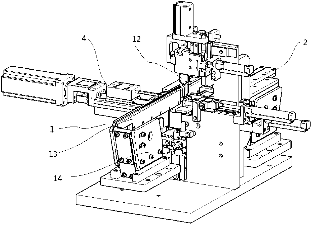
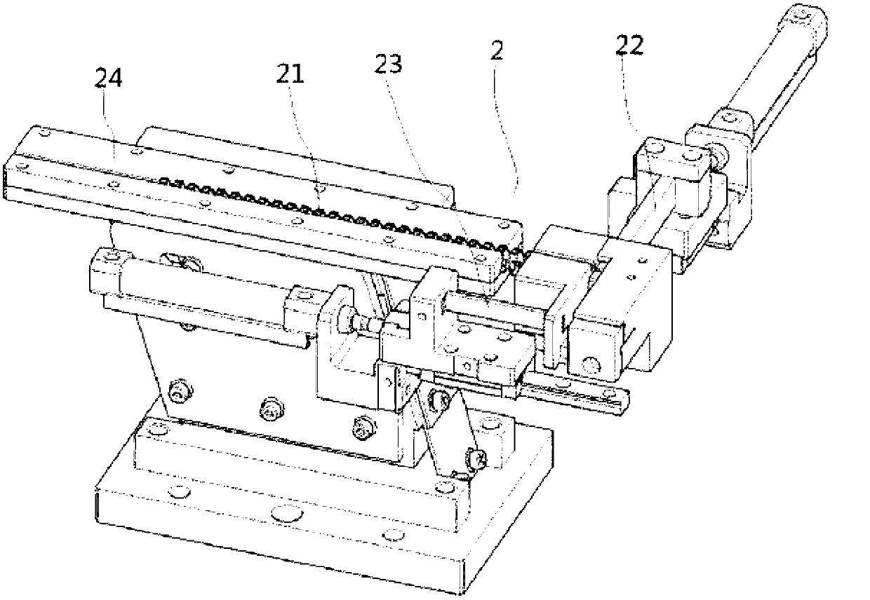
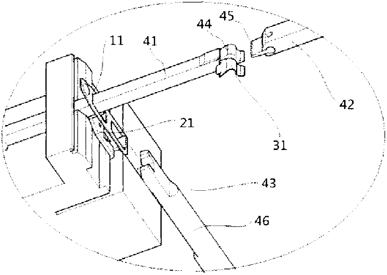
[0049] Examples, see Figure 1 to Figure 10 , the automatic assembly method of the micro switch shrapnel provided by the present invention, it comprises the following steps:

[0050] (1) Prepare materials, prepare the C pin 21 of the micro switch shrapnel, the shrapnel 11 and the bridge 31;

[0051] (2) A micro switch shrapnel automatic assembly device is set, which device includes shrapnel feeding mechanism 1, C-leg feeding mechanism 2, bridging feeding mechanism 3 and shrapnel assembly mechanism 4, and the C-leg feeding mechanism 2 includes a first push rod 22 and The second push rod 23, the shrapnel feeding mechanism 1 includes a clamping manipulator 12 and a shrapnel feeding channel 13, the clamping manipulator 12 is located above the shrapnel assembly mechanism 4, and the shrapnel feeding channel 13 pushes the shrapnel 11 in a vertical direction. Or arranged in an inclined direction and transport the shrapnel 11 to the below of the clamping manipulator 12 in the horizontal...


PUM


Abstract

The invention discloses an automated assembly method of microswitch shrapnel. The method comprises a first step of preparing material; a second step of setting an automated assembly of the micorswitch shrapnel; a third step that C foot is put above the shrapnel positioning device by a C-foot feed mechanism in the automated assembly of a microswitch shrapnel; a forth step that the shrapnel is clamped by a clamping mechanical arm and the shrapnel is blocked inside the C foot; a fifth step that a positioning pushrod sustains the shrapnel and locates the shrapnel in the C foot; a sixth step that a third push rod penetrates above the C foot into a through hole which is on the shrapnel; a seventh step that a bridging teed mechanism transmits the bridging to a groove which is installed on the head of the third pushrod; a eighth step that the third pushrod and the forth pushrod push synchronously the shrapnel into a box out between the bridges; a ninth step that each mechanism returns to a initial position; a tenth step of repeating from the third step to the ninth step achieving the automated assembly of the microswitch shrapnel. The automated assembly further discloses a carrying-out device of the automated assembly.

Description

technical field [0001] The present invention relates to the technical field of an automatic assembly method for a micro switch, in particular to an automatic assembly method for a micro switch shrapnel, and also relates to an automatic assembly device for a micro switch shrapnel. Background technique [0002] A micro switch, also known as a sensitive switch, is a contact mechanism with a small contact interval and a snap-action mechanism that performs switching actions with a specified stroke and a specified force. It is covered with a casing and has a drive rod outside. At present, the micro switches on the domestic market have different mechanical life spans from 3W to 1000W, generally 10W, 20W, 50W, 100W, 300W, 500W, and 800W, which are generally used in China. The reeds are made of beryllium bronze, tin bronze, and stainless steel wire. Foreign ALPS can achieve a maximum of 1000W times. Their reeds are made of rare metal titanium. [0003] The traditional assembly of mi...

Claims


Application Information

Patent Timeline
IPC IPC(8): B23P21/00
Inventor 刘贤辉
Owner 东莞市焦点自动化科技有限公司
Learn More