
Personalized lumbar internal fixation auxiliary device and manufacturing method thereof

An auxiliary device and lumbar spine technology, applied in the field of medical equipment, can solve the problems of easy error in the registration of the vertebral body surface, high requirements for equipment, and long learning period, etc., and achieve the effects of reducing the risk of exposure infection, shortening the operation time, and convenient disinfection

Active Publication Date: 2013-05-15
PEKING UNION MEDICAL COLLEGE HOSPITAL CHINESE ACAD OF MEDICAL SCI
View PDF5 Cites 16 Cited by
  • Summary
  • Abstract
  • Description
  • Claims
  • Application Information

AI Technical Summary

Problems solved by technology

However, the positioning and navigation equipment for spinal pedicles is expensive, requires high equipment, takes a long learning period, and is prone to errors when registering on the surface of the vertebral body. Nail setting method with equal advantages

Method used

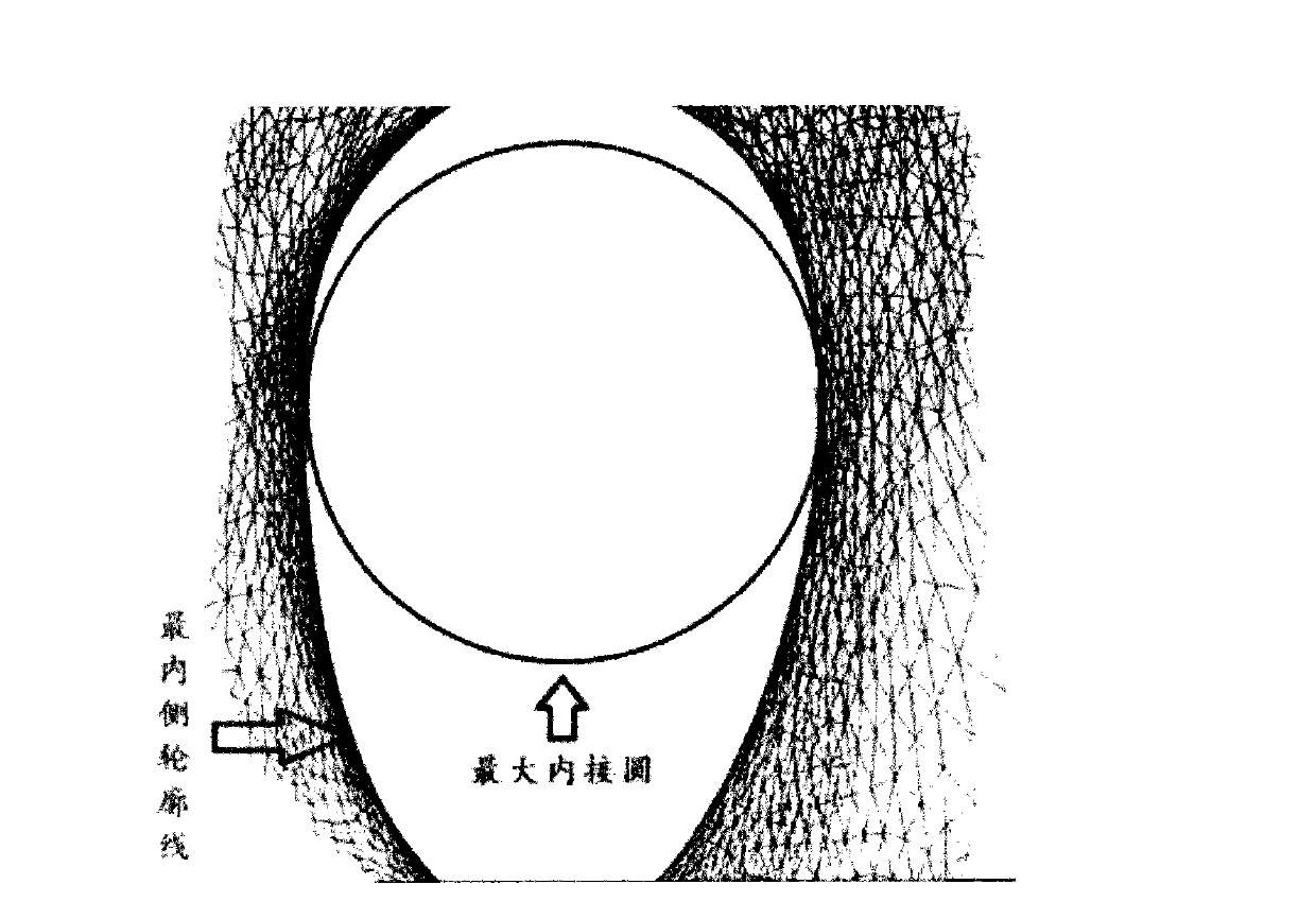
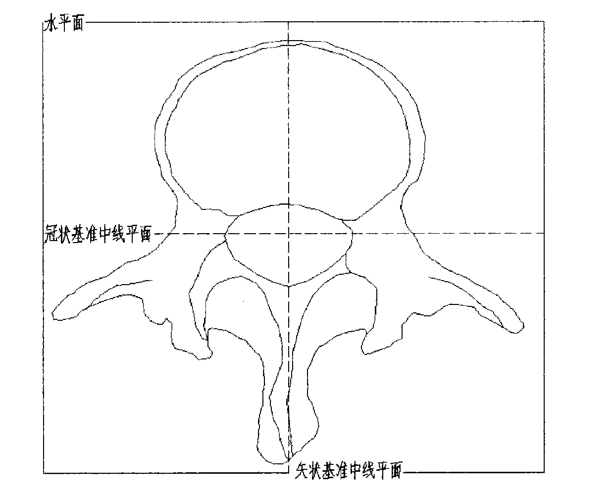
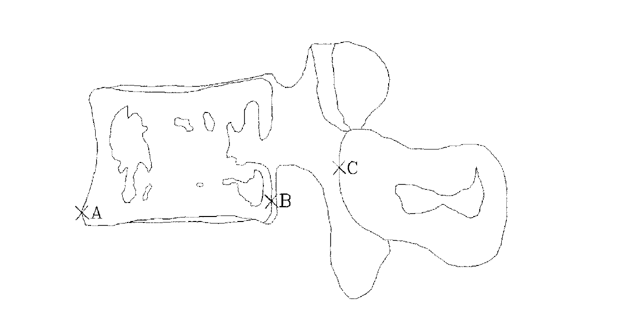

Image

  • Personalized lumbar internal fixation auxiliary device and manufacturing method thereof
  • Personalized lumbar internal fixation auxiliary device and manufacturing method thereof
  • Personalized lumbar internal fixation auxiliary device and manufacturing method thereof

Examples


Embodiment 1

[0040] Embodiment 1 Structural description of personalized lumbar internal fixation auxiliary device

[0041] Such as Figure 6 As shown, the personalized lumbar internal fixation auxiliary device of the present invention includes: a guide hole 1, a connecting body 2, and a sleeve 3, the guide hole 1 is two, the sleeve 2 is two, and the connecting body connects two guide hole.

[0042] Among them, the casing is multi-standard, and its outer diameter is the same as the length of the guide hole; the inner diameter of the casing has various sizes according to the requirements, and the inner diameter of the casing is preferably 0.5-20mm; when used, the casing is inserted into the guide hole. In the hole, replace the cannula of different specifications according to the operation needs.

[0043] The surface of the connecting body is a structure that can complementarily connect with the surface of the posterior vertebral plate and the spinous process of the vertebral body.

Embodiment 2

[0044] Example 2 Preparation of Personalized Lumbar Internal Fixation Auxiliary Device

[0045] 1. Materials and methods

[0046] 1. Materials

[0047] One normal adult isolated lumbar vertebral dry bone specimen treated with 10% formalin was taken, and its attached soft tissue structures were dissected and removed. The specimens were provided by the Department of Anatomy, Peking Union Medical College.

[0048] SIEMENS / Sensation 64-slice CT machine, scanning parameters: slice thickness 2mm, slice distance 2mm, tube voltage 120kV, current 225mAs, resolution 512*512pxl

[0049] Objet EDEN250 3D reconstruction printer, technical parameters: molding resolution X-axis: 600dpi: 42u, Y-axis: 300dpi: 84u, Z-axis: 1600dpi: 16u, accuracy 0.1-0.2mm (accuracy depends on object shape, part use and printing size ), power supply 110-240VAC50 / 60Hz1.5KW, operating environment 18-25℃, relative humidity 30%-70%

[0050] FullCure720: Objet's medical transparent molding material.

[0051] 2. ...


PUM

PropertyMeasurementUnit
The inside diameter ofaaaaaaaaaa
Lengthaaaaaaaaaa

Abstract

The invention relates to a personalized lumber internal fixation auxiliary device and a manufacturing method thereof. The personalized lumber internal fixation auxiliary device comprises two guide holes, two sleeve pipes and a connector, wherein the sleeve pipes are positioned in the guide holes, and the connector is connected with the guide holes on two sides. The manufacturing method comprises the following steps of: firstly, acquiring lumbar three-dimensional parameters through CT (computed tomography) scanning; secondly, designing a guide plate containing positioning guide holes for vertebral pedicles on two sides of a single vertebral body on a three-dimensionally reconstructed lumbar digital anatomical model; and finally, producing a template through a laser radiation layer-by-layer solidification forming technology. The personalized lumber internal fixation auxiliary device is used for accurate implantation of pedicle screws.

Description

technical field [0001] The present invention relates to the field of medical devices, in particular to a personalized lumbar internal fixation auxiliary device and a preparation method thereof. The method uses self-computer-aided design technology, reverse engineering technology and rapid prototyping technology. Auxiliary device for accurate placement of pedicle screws. Background technique [0002] Biomechanical experiments have proved that only when the screw is accurately placed along the only anatomical long-axis channel of the pedicle and reaches the ideal depth, can the stability of the screw-rod system and ideal clinical efficacy be guaranteed [LAW M, TENCER AF, ANDERSON P A.Caudo -cephalad loading of pedicle screws: mechanisms of loosening and methods of augmentation. Spine, 1993, 18(16): 2438-2443], this uniqueness leads to increased difficulty of operation. In order to improve the accuracy of pedicle screw placement, scholars at home and abroad have conducted many...

Claims


Application Information

Patent Timeline
IPC IPC(8): A61B19/00A61B17/70
Inventor 吴志宏王以朋孙小虎邱贵兴
Owner PEKING UNION MEDICAL COLLEGE HOSPITAL CHINESE ACAD OF MEDICAL SCI
Learn More