Telescopic seedling transplanter

A technology of seedlings and main rod sleeves, which is applied in the field of agricultural tools, can solve the problems of increasing the friction between the pin and the splint, increasing the labor intensity of the operator, and reducing the mechanical efficiency of the device, so as to eliminate friction, avoid uneven force, even force effect

Inactive Publication Date: 2015-01-07
NINGBO YINZHOU YUNFAN ENG CONSULTING
View PDF5 Cites 2 Cited by
  • Summary
  • Abstract
  • Description
  • Claims
  • Application Information

AI Technical Summary

Problems solved by technology

[0003] 1. Since the pin is located at the left end of the splint, and the pull wire is located at the right end of the splint, during the process of pulling the splint, since the direction of the pulling force is not consistent with the axis of the pin, a torque will be generated on the splint, which will increase the tension between the pin and the splint. The friction between them reduces the flexibility of the device on the one hand, and reduces the mechanical efficiency of the device on the other hand.
[0004] 2. Since the telescopic rod is a straight rod, there is no turning point, and the clamp of the splint can not be adjusted at any angle, which makes the operator bend over as far as possible and hold the splint in order to keep the clamp of the splint vertical. The handle and telescopic rod are at a lower position, which undoubtedly increases the labor intensity of the operator and also makes the operation very inconvenient
[0005] 3. Although a sponge is arranged on the close-fitting surface of the two splints in this plan, since the stem of the seedling is circular, the planar sponge will still cause certain damage to the seedling due to uneven pressure during the process of compressing the sponge.

Method used


Image

  • Telescopic seedling transplanter
  • Telescopic seedling transplanter

Examples


Embodiment Construction

[0024] The present invention will be further described below in conjunction with the accompanying drawings and embodiments.

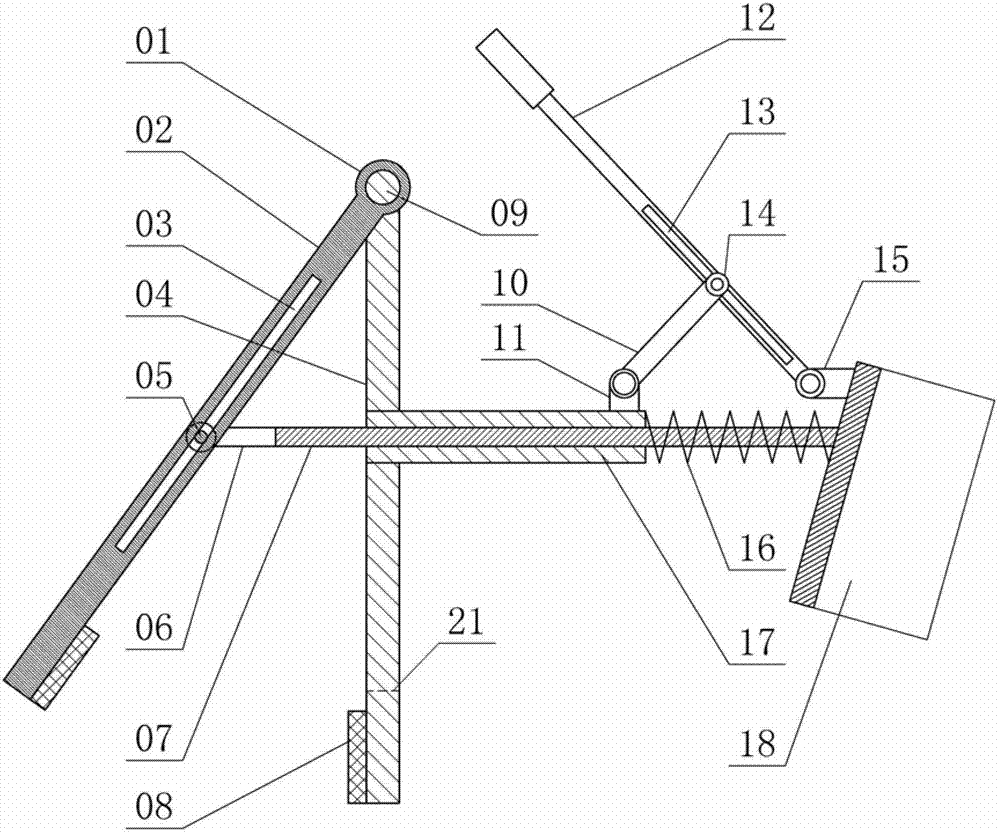
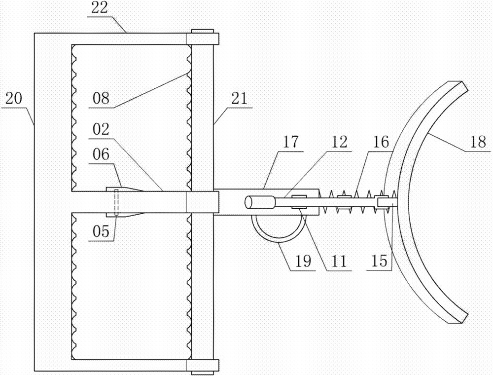
[0025] The telescopic rice seedling transplanter consists of a shaft sleeve 01, a middle forearm 02, a chute 03, a middle rear arm 04, a sliding shaft 05, a shaft fork 06, a main rod 07, a toothed pad 08, a top shaft 09, a pull rod 10, and a rotating shaft seat 11. Operating handle 12, handle chute 13, pulley 14, handle shaft seat 15, spring 16, main rod cover 17, waist support 18, handle 19, front clip 20 and rear clip 21 constitute.

[0026] Wherein, the two sections of side arms 22, the middle forearm 02 between the two sides of the arms 22, and the front clip 20 combined with the lower ends of the side arms 22 and the middle forearm 02 jointly form an E-shaped front half of the frame body; the other two sections of sides The arm 22, the middle rear arm 04 between the two side arms 22 and the rear clip 21 integrated with the lower ends of the side ar...


PUM


Abstract

The invention relates to a farming tool and particularly relates to a telescopic seedling transplanter. The telescopic seedling transplanter consists of a shaft sleeve, a middle front arm, a sliding chute, a middle rear arm, a sliding shaft, a shaft fork, a main rod, a tooth-shaped gasket, a top shaft, a pull rod, a rotating shaft seat, an operating handle, a handle sliding chute, a pulley, a handle shaft seat, a spring, a main rod sleeve, a waist pad, a handle, a front clamp and a rear clamp, wherein the middle front arm is provided with the sliding chute, the sliding shaft is positioned in the sliding chute and can slide in the sliding chute, the left end of the main rod is provided with the shaft fork which is integrated with the main rod, the ends of two forks of the shaft fork are respectively combined with two ends of the sliding shaft, the right end of the main rod passes through the main rod sleeve and is combined with the arc-shaped waist pad into a whole, and the spring is sheathed on the part, positioned between the right end of the main rod sleeve and the waist pad, of the main rod. The telescopic seedling transplanter can be used for reducing the labor intensity of an operator, and improving the transplanting efficiency and transplanting survival rate.

Description

technical field [0001] The invention relates to an agricultural tool, in particular to a telescopic seedling transplanter. Background technique [0002] The patent No. 200810155822.1 "a kind of rice seedling transplanter" pulls the movable splint through the stay wire to achieve the effect of improving the operation efficiency, but the solution has the following technical defects: [0003] 1. Since the pin is located at the left end of the splint, and the pull wire is located at the right end of the splint, during the process of pulling the splint, since the direction of the pulling force is not consistent with the axis of the pin, a torque will be generated on the splint, which will increase the tension between the pin and the splint. The friction between them reduces the flexibility of the device on the one hand, and reduces the mechanical efficiency of the device on the other hand. [0004] 2. Since the telescopic rod is a straight rod, there is no turning point, and the...

Claims


Application Information

Patent Timeline
Patent Type & Authority Patents(China)
IPC IPC(8): A01C11/02
Inventor 梁德富
Owner NINGBO YINZHOU YUNFAN ENG CONSULTING
Why Eureka
Try Eureka