
Input Shaft Damper Of Transmission

A technology for input shafts and transmissions, applied to components with teeth, springs/shock absorbers, gear transmissions, etc., can solve the problems of installation position or its space limitation, ISD volume increase, etc.

Active Publication Date: 2013-05-08
HYUNDAI MOTOR CO LTD
View PDF6 Cites 3 Cited by
  • Summary
  • Abstract
  • Description
  • Claims
  • Application Information

AI Technical Summary

Problems solved by technology

In order to provide large inertia and rigidity to the input shaft by the usual method, the volume of the ISD is significantly increased, and therefore, the installation position or its space is subject to many restrictions

Method used


Image

  • Input Shaft Damper Of Transmission
  • Input Shaft Damper Of Transmission

Examples


Embodiment Construction

[0019] Reference hereafter will be made in detail to various embodiments of the invention, examples of which are shown in the accompanying drawings and described below. While the invention has been described in connection with the preferred embodiments, it will be understood that present description is not intended to limit the invention to those preferred embodiments. On the contrary, the invention is intended to cover not only the preferred embodiments, but also various alternatives, modifications, equivalents and other embodiments, which may be included within the spirit and scope of the invention as defined by the appended claims.

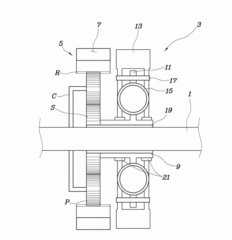
[0020] refer to figure 1 with 2 , the ISD according to the exemplary embodiment of the present invention is configured to include an inertial body assembly 3 relatively rotatably mounted on the input shaft 1 of the transmission; and a planetary gear set 5, the planetary gear A group 5 is installed on the input shaft 1 to receive and increase...


PUM


Abstract

An input shaft damper (ISD) of a transmission, may include an inertia body assembly relatively rotatably mounted on an input shaft of the transmission, and a planetary gear set mounted on the input shaft so as to receive and increase a rotational force of the input shaft and output an increased rotational force to the inertial body assembly.

Description

[0001] Cross References to Related Applications [0002] This application claims priority from Korean Patent Application No. 10-2011-0112030 filed on Oct. 31, 2011, the entire contents of which are hereby incorporated by reference for all purposes. technical field [0003] The present invention relates to an input shaft damper of a transmission, and more particularly to a technique for reducing rattle noise of a transmission by imparting additional inertia to the input shaft of the transmission to avoid resonance in a specific RPM region. Background technique [0004] As described in the following literature, the resonance at a particular RPM band that causes rattling noise in transmissions that do not use a dual mass flywheel (DMF) can be effectively avoided by including an input shaft damper (ISD), which damps The transmission is configured to mount the inertia plate on the input shaft of the transmission. [0005] However, in order for the ISD to obtain a suitable effect...

Claims


Application Information

Patent Timeline
IPC IPC(8): F16H57/028
CPCF16F15/14Y02E70/30F16F15/1478Y10T74/2131F16H57/02F16H1/28
Inventor 黄载雄陈用郁吴浣守
Owner HYUNDAI MOTOR CO LTD
Learn More