
Hydraulic well sealing device

A well sealing device and hydraulic technology, which is applied in sealing/isolation, wellbore/well parts, earthwork drilling and production, etc., can solve problems such as poor sealing performance, increased cost, and small application range, and achieve high sealing pressure and reduced Operating cost and long service life

Inactive Publication Date: 2013-05-08
濮阳市中发石油机械有限公司
View PDF5 Cites 2 Cited by
  • Summary
  • Abstract
  • Description
  • Claims
  • Application Information

AI Technical Summary

Problems solved by technology

[0003] The purpose of the present invention is to provide a hydraulic sealer with a simple structure to overcome the defects of the existing sealer such as small application range and poor sealing performance. Dynamic sealing, more effectively reduce environmental pollution, ensure the smooth completion of operations, and avoid cost increases

Method used


Image

  • Hydraulic well sealing device
  • Hydraulic well sealing device

Examples


Embodiment Construction

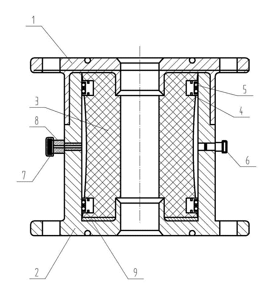
[0015] Such as figure 1 As shown, the hydraulic sealer includes an upper body and a lower body. The upper body and the lower body are connected to form an "I" shape, and the rubber cylinder is placed in the space formed by the upper body and the lower body. A rubber cartridge skeleton is arranged between the rubber cartridge body and the lower body, and the rubber cartridge skeleton is combined with the lower body through an O-ring to form a closed annular space. A joint is arranged on one side of the lower body. The joints are correspondingly provided with joint pressing caps. A silk plug is also arranged on the lower body. A backing plate is arranged at the joint between the rubber cylinder body and the lower body.

[0016] The rubber cylinder skeleton at the upper and lower ends of the rubber cylinder body of the hydraulic well sealing device of the present invention is sealed into an annular space by combining the O-shaped sealing ring and the lower body, and the hydra...


PUM


Abstract

The invention relates to a wellhead hydraulic automatic sealing device, in particular to a hydraulic well sealing device. The hydraulic well sealing device comprises an upper body and a lower body. The upper body and the lower body are connected to form an H shape. A rubber cylinder body is further connected with the upper body and the lower body. A rubber cylinder frame is arranged between the rubber cylinder body and the lower body. The rubber cylinder frame is combined with the lower body through an O-shaped sealing ring to form a closed annular space. One side of the lower body is provided with a joint. The hydraulic well sealing device is high in sealing pressure and a safety factor, simple in structure, convenient to install, favorable for pressure discharging, capable of reducing environment pollution, improving production efficiency and reducing operation cost, long in service life and reusable.

Description

technical field [0001] The invention relates to a wellhead hydraulic self-sealing device, in particular to a hydraulic well sealing device. Background technique [0002] In the process of exploration and development of oil and gas fields, there are always some oil and water wells that are temporarily or permanently shut down due to low energy, high water content, downhole accidents, geological or engineering factors, and no use value. Or non-hydraulic sealing well, neither economical nor safe. Sometimes under certain technical conditions, after measures such as injection-production improvement, adjustment, overhaul, drilling plug, sleeve removal and sleeve replacement, it needs to be redeveloped and utilized. At this time, it is time-consuming and uneconomical to drill or scrape off the ash plug. In order to protect this type of well from being damaged and causing no environmental pollution during the well shut-in process and can be reused, a new well sealing device is to ...

Claims


Application Information

Patent Timeline
Patent Type & Authority Applications(China)
IPC IPC(8): E21B33/03
Inventor 王红军钟仲良
Owner 濮阳市中发石油机械有限公司
Learn More