
Separation blade dismantling jig

A technology of baffles and jigs, which is applied in the field of jigs, can solve the problems of affecting the appearance and performance of the chassis, time-consuming operation of dismantling the baffles, and high dismantling costs, so as to achieve undamaged appearance and working performance, saving man-hours, and simple operation Effect

Inactive Publication Date: 2013-05-08
HONG FU JIN PRECISION IND WUHAN CO LTD +1
View PDF5 Cites 1 Cited by
  • Summary
  • Abstract
  • Description
  • Claims
  • Application Information

AI Technical Summary

Problems solved by technology

In this way, the removal of the baffle is time-consuming and costly, and the screwdriver is easy to squeeze other parts of the chassis during the large-angle swing process, resulting in deformation of the chassis and affecting the appearance and performance of the chassis

Method used


Image

  • Separation blade dismantling jig
  • Separation blade dismantling jig
  • Separation blade dismantling jig

Examples


Embodiment Construction

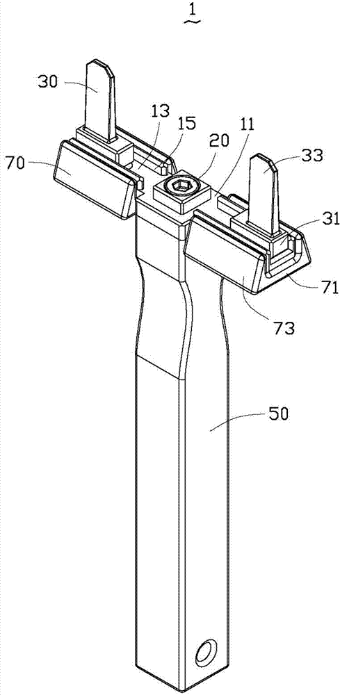
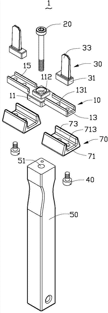
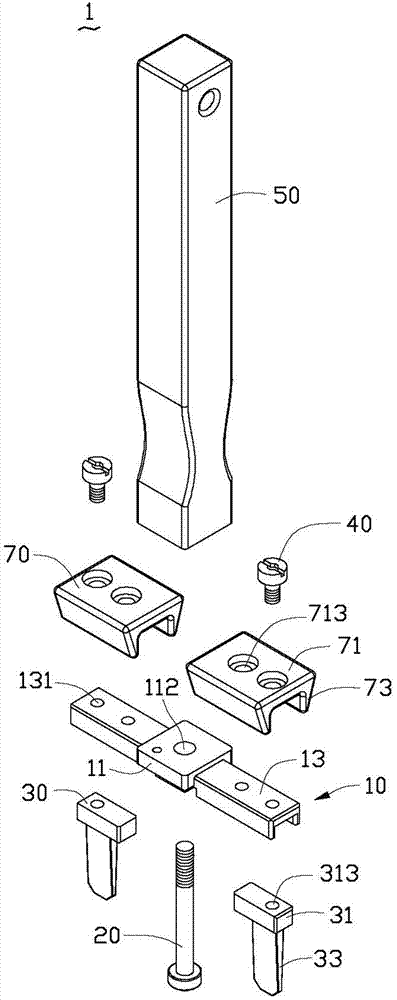
[0013] see figure 1 and Figure 4 , The block removal jig 1 of the present invention is used to remove the block 3 of the chassis 2 of the desktop computer, so as to install the expansion card port. The jig 1 for removing the baffle can also be used to remove the baffles of the cabinets of servers and other similar electronic products. The blocking piece removal jig 1 includes a bracket 10 , two picks 30 mounted on opposite ends of the top surface of the bracket 10 , and a handle 50 mounted on the middle of the bottom surface of the bracket 10 . The two skids 30 can be installed at different positions of the bracket 10 , so as to adjust the distance between the two skids 30 , so that the two skids 30 can fit the two openings 4 of the blocking pieces 3 of different sizes. The handle 50 is used for the convenience of the operator to operate the jig 1 for removing the blocking sheet.

[0014] Please also see figure 2 and image 3 , the bracket 10 includes a joint portion 11...


PUM


Abstract

A separation blade dismantling jig is used for dismantling separation blades with openings on a computer case and comprises a support and a handle installed at the bottom surface of the support. The separation blade dismantling jig further comprises two separated prizing sheets installed at the top of the support, wherein the two prizing sheets are used for being inserted into two openings of the separation blades. The separation blade dismantling jig is matched with one separation blade simultaneously through two prizing sheets, and the action force exerted onto the separation blades by the separation blade dismantling jig is large in area and relatively even, so that the separation blades can be dismantled from the computer case by slightly swinging the separation blade dismantling jig for a small angle. The separation blade dismantling jig is easy to operate, saves working hour, can reduce the collision opportunity between the separation blade dismantling jig and the computer case and prevents the appearance and the working performance of the case from being damaged.

Description

technical field [0001] The invention relates to a jig, in particular to a jig for removing a jig for dismantling a jig of an electronic product case. Background technique [0002] Now various electronic products such as desktop computers have more and more advanced configurations, more and more functions, and more and more various expansion cards are used. For this reason, all kinds of blanks reserved on the chassis need to be removed in order to install the corresponding interface of the expansion card. The industry usually inserts a flat-head screwdriver into an opening of the corresponding blocking plate, and then swings the screwdriver left and right to make the blocking plate disengage from the chassis. However, in the process of operation, it is necessary to swing the screwdriver with a large angle for many times before the blocking plate can be disassembled. In this way, the removal of the baffle is time-consuming and costly, and the screwdriver is easy to squeeze o...

Claims


Application Information

Patent Timeline
Patent Type & Authority Applications(China)
IPC IPC(8): B25B27/00
CPCB25B27/00Y10T29/53283
Inventor 叶锦文彭志坚肖扬周敦军
Owner HONG FU JIN PRECISION IND WUHAN CO LTD
Learn More