
Waste incineration ash slag cooling machine

A waste incineration ash and slag cooling technology, applied in the direction of incinerators, combustion methods, combustion types, etc., can solve the problems of large water consumption, fast wear of water tanks, equipment corrosion, etc., to achieve energy saving, thorough cooling, and avoid blockage effects

Inactive Publication Date: 2013-05-01
CITIC HEAVY INDUSTRIES CO LTD
View PDF10 Cites 2 Cited by
  • Summary
  • Abstract
  • Description
  • Claims
  • Application Information

AI Technical Summary

Problems solved by technology

[0002] At present, the commonly used waste incineration ash coolers are usually divided into three types according to the different slag discharge mechanisms: ash pusher, scraper slag remover and spiral slag remover. The working principles of these three ash slag coolers are very Similar, they all use the water-cooling cooling method, that is, the high-temperature ash is discharged from the incinerator and directly falls into the water tank, and after being cooled by water, it is discharged from the cooler by the slag discharge mechanism; although this type of cooler has a better cooling effect, its Low thermal efficiency, large water consumption, fast wear of the water tank, and serious equipment corrosion
In addition, because the cooling water leaches a large amount of toxic substances such as heavy metals from the high-temperature garbage ash, the environmental pollution caused by this type of cooler is relatively serious

Method used


Image

  • Waste incineration ash slag cooling machine

Examples


Embodiment Construction

[0020] The technical solutions of the present invention will be further described in detail below in conjunction with the accompanying drawings and embodiments.

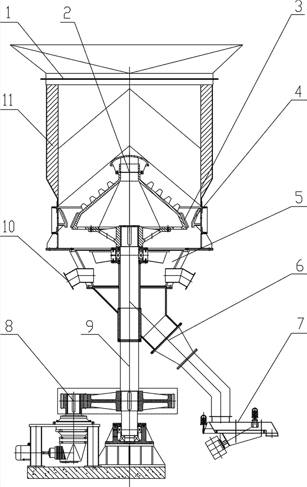
[0021] Such as figure 1 As shown, the waste incineration ash cooler includes a housing 1, a pan tower 2, a lower bin 5, a discharge pipe 6, a vibrating conveyor 7, a vertical shaft 9 and a driving device 8, the housing 1 The bottom port is fixedly connected with the upper port of the lower silo 5, the side wall of the lower hopper 5 is provided with a cooling air inlet 10, the lower port of the lower hopper 5 is fixedly connected with one end of the discharge pipe 6, and the outlet pipe 6 The other end is connected with the vibrating conveyor 7, and the housing 1 is provided with a pan tower 2, the outer surface of the pan tower 2 is a conical surface, and the outer surface of the pan tower 2 is provided with a ring near the bottom end. The tooth plate A 3, the annular tooth plate A 3 is provided with the annular to...


PUM


Abstract

The invention discloses a waste incineration ash slag cooling machine, which comprises a casing, a disc tower, a baiting cabin, a discharging pipe, a vibration conveyor, a vertical shaft and a driving device, wherein a bottom end opening of the casing is fixedly connected with an upper end opening of the baiting cabin, a cooling air inlet is arranged in the side wall of the baiting cabin, a lower end opening of the baiting cabin is fixedly connected with one end of the discharge pipe, the other end of the discharging pipe is connected with the vibration conveyor, the disc tower is arranged in the casing, the outer surface of the disc tower is in a conical surface, an annular tooth plate A is arranged in a position on the outer surface of the disc tower near the bottom end, an annular tooth plate B is arranged in a position of the annular tooth plate A corresponding to the inner wall of the casing, a wedge-shaped space gradually reduced from top to bottom is formed between the annular tooth plate A and the annular tooth plate B, the disc tower is fixedly connected onto one end of the vertical shaft, and the other end of the vertical shaft is connected with the driving device. The waste incineration ash slag cooling machine has the advantages that high-temperature ash slag can be fast cooled, massive ahs slag can also be crushed into small blocks, the energy is saved, and the environment is protected.

Description

technical field [0001] The invention relates to a garbage incineration ash cooler, which is used for cooling and crushing high-temperature ash discharged from an incinerator. Background technique [0002] At present, the commonly used waste incineration ash coolers are usually divided into three types according to the different slag discharge mechanisms: ash pusher, scraper slag remover and spiral slag remover. The working principles of these three ash slag coolers are very Similar, they all use the water-cooling cooling method, that is, the high-temperature ash is discharged from the incinerator and directly falls into the water tank, and after being cooled by water, it is discharged from the cooler by the slag discharge mechanism; although this type of cooler has a better cooling effect, its The thermal efficiency is low, the water consumption is large, the sink wears out quickly, and the equipment is seriously corroded. In addition, because the cooling water leaches a la...

Claims


Application Information

Patent Timeline
Patent Type & Authority Applications(China)
IPC IPC(8): F23G5/44F23G5/46F23L15/00F23J1/06
CPCY02E20/34
Inventor 王凯朱雯陈士超
Owner CITIC HEAVY INDUSTRIES CO LTD
Learn More