
Air inlet pipe of integrated intercooler

An air intake pipe and intercooler technology, which is applied in the field of air intake pipes integrated with intercoolers, can solve the problems of unfavorable arrangement of other components of the engine, unfavorable installation and disassembly of the air intake system, and large space occupied by the air intake system. Conducive to intake air charge, saving layout space and improving work performance

Active Publication Date: 2013-05-01
CHINA NORTH ENGINE INST TIANJIN
View PDF6 Cites 8 Cited by
  • Summary
  • Abstract
  • Description
  • Claims
  • Application Information

AI Technical Summary

Problems solved by technology

[0005] Aiming at the technical problems that the air intake system occupies too much space in the prior art, which is not conducive to the arrangement of other parts of the engine, is not conducive to the installation and disassembly of the intake system, and has poor transient response of the engine, the invention proposes an integrated intercooler air intake pipe

Method used


Image

  • Air inlet pipe of integrated intercooler
  • Air inlet pipe of integrated intercooler
  • Air inlet pipe of integrated intercooler

Examples


Embodiment Construction

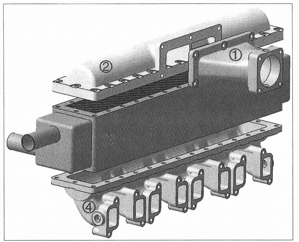
[0013] Such as figure 1 As shown, after the external fresh air is pressurized, it enters the upper air intake chamber 2 from the compressor outlet through the transition pipe 1, then enters the intercooler 3, cools down in the intercooler 3, and finally passes through the lower air intake chamber The intake manifold of 4 enters the cylinders of the engine to participate in combustion.

[0014] The upper air intake cavity partition is arranged inside the upper air intake cavity 2, so that the pressurized air evenly enters the intercooler to realize uniform cooling.

[0015] The upper air intake chamber partition is arranged in the middle of the upper air intake chamber 2, so that the pressurized air enters the left and right parts of the intercooler evenly to achieve uniform cooling.

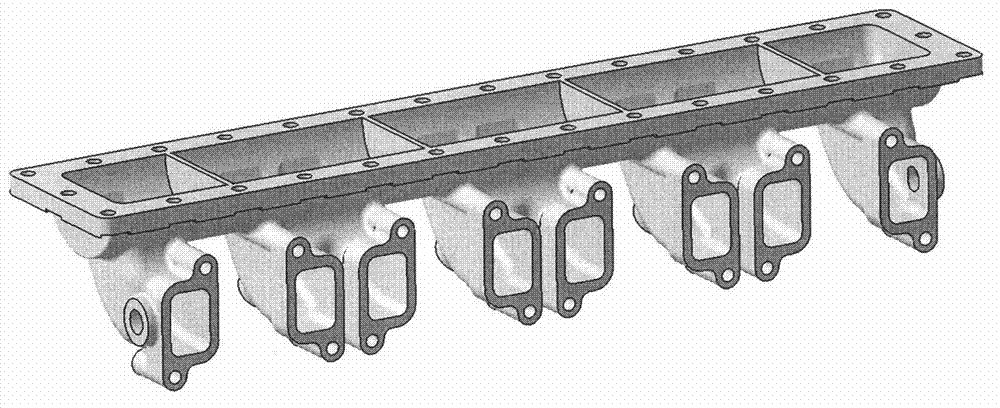
[0016] The lower air intake chamber baffle is arranged inside the lower air intake chamber 4, so that the cooled pressurized air enters each cylinder on average, realizes uniform air intake, and...


PUM


Abstract

The invention relates to an air inlet pipe of an integrated intercooler, comprising a transition pipe 1, an upper side air inlet cavity 2, an intercooler 3 and a lower side air inlet cavity 4, wherein an inlet of the transition pipe 1 is connected with an outlet of a compressor; an outlet of the transition pipe 1 is connected with an inlet of the upper side air inlet cavity 2; and the intercooler 3 is embedded between the upper side air inlet cavity 2 and the lower side air inlet cavity 4. After being pressurized by the compressor, external fresh air enters the upper side air inlet cavity 2 from the outlet of the compressor through the transition pipe 1, enters the intercooler 3 for cooling, and finally enters an air cylinder of an engine for combustion through an air inlet manifold of the lower side air inlet cavity 4. With the adoption of the air inlet pipe of the integrated intercooler disclosed by the invention, not only can an arrangement space be saved, the length of a pipeline from an outlet of the compressor and an inlet of an air inlet path be greatly reduced, the working properties of a supercharged diesel engine be improved, and the quality of the engine be reduced; but also the volume of an air inlet system is reduced, the air inlet uniformity is improved, and the transient response property of the engine is improved. Pressure fluctuation inside the air inlet manifold is less due to the voltage stabilization and filtering effect of an intercooler core, so that the air inlet pipe of the integrated intercooler is more beneficial to improving an air inlet filling amount and an air inlet vortex quality.

Description

technical field [0001] The invention relates to an engine intake pipe, in particular to an intake pipe integrated with an intercooler. Background technique [0002] Modern diesel engines generally adopt air intake supercharging technology. The role of supercharging technology is very obvious. In the case of a certain cylinder volume, the greater the air charge density, the greater the absolute amount of fresh air, more fuel can be injected for combustion, and the engine can generate greater power. However, the increase in air temperature after compression in the supercharging device will lead to a decrease in air density, that is, the increase in the air density ratio is smaller than the increase in the pressure ratio, thus affecting the performance of the supercharging effect. [0003] In order to enhance the supercharging effect, especially in the case of high supercharging, it is necessary to adopt air intake cooling measures, which is usually called intercooling. In ad...

Claims


Application Information

Patent Timeline
Patent Type & Authority Applications(China)
IPC IPC(8): F02M35/104F02B29/04
CPCY02T10/146Y02T10/12
Inventor 殷玉恩刘胜梁红波卞尔保梁永森
Owner CHINA NORTH ENGINE INST TIANJIN
Learn More