
Internal combustion engine with injection valve

An engine and injection valve technology, applied in the direction of engine components, machines/engines, fuel injection devices, etc., can solve the problems of complexity, valve retention, etc., and achieve the effect of low cost

Inactive Publication Date: 2013-04-24
AUDI AG
View PDF14 Cites 0 Cited by
  • Summary
  • Abstract
  • Description
  • Claims
  • Application Information

AI Technical Summary

Problems solved by technology

However, this rotational fixation cannot keep the valve in a given position in all operating conditions, and it also changes complicatedly when the geometrical characteristics of the injection valve or the cylinder head itself change

Method used


Image

  • Internal combustion engine with injection valve
  • Internal combustion engine with injection valve
  • Internal combustion engine with injection valve

Examples


Embodiment Construction

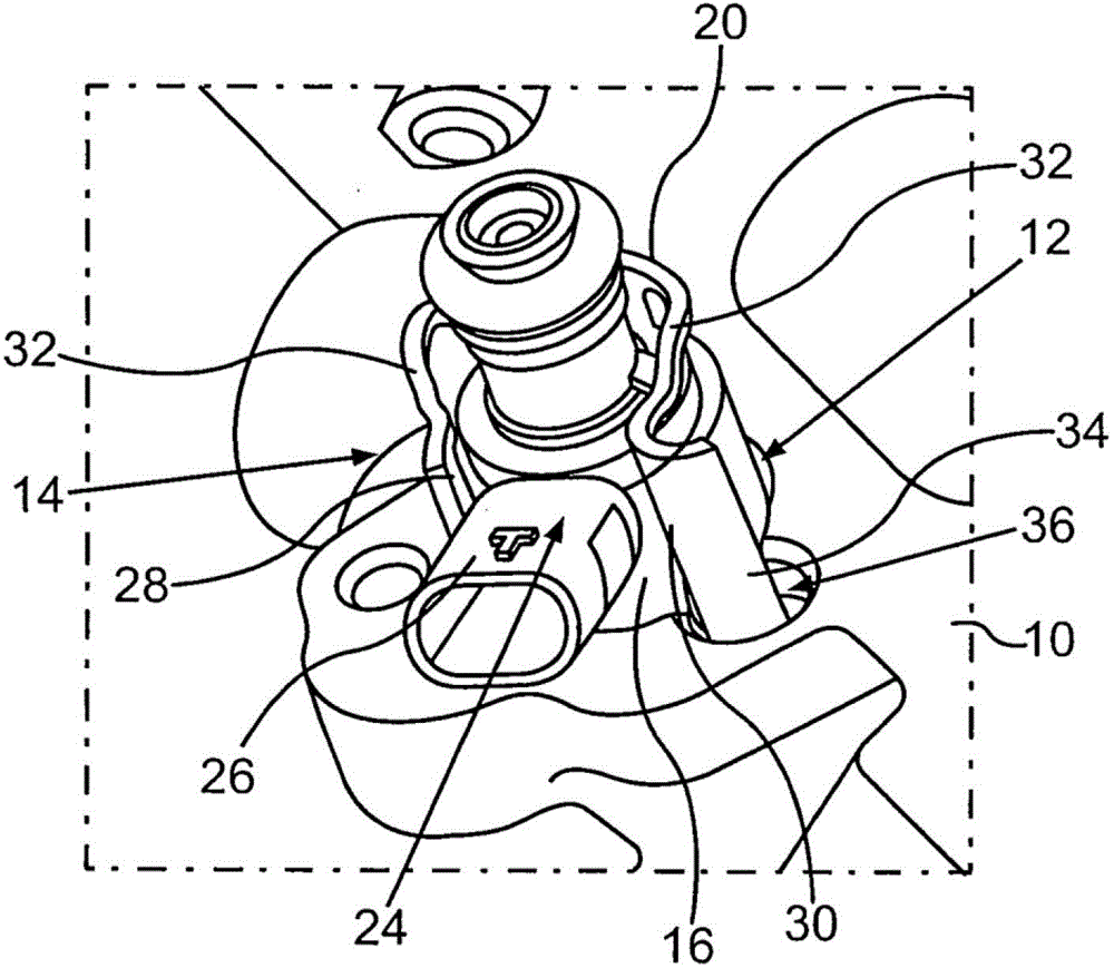
[0023] figure 1 A perspective view of a detail of a cylinder head 10 for an engine is shown. Cylinder head 10 has receiving bores 12 for injection valves 14 .

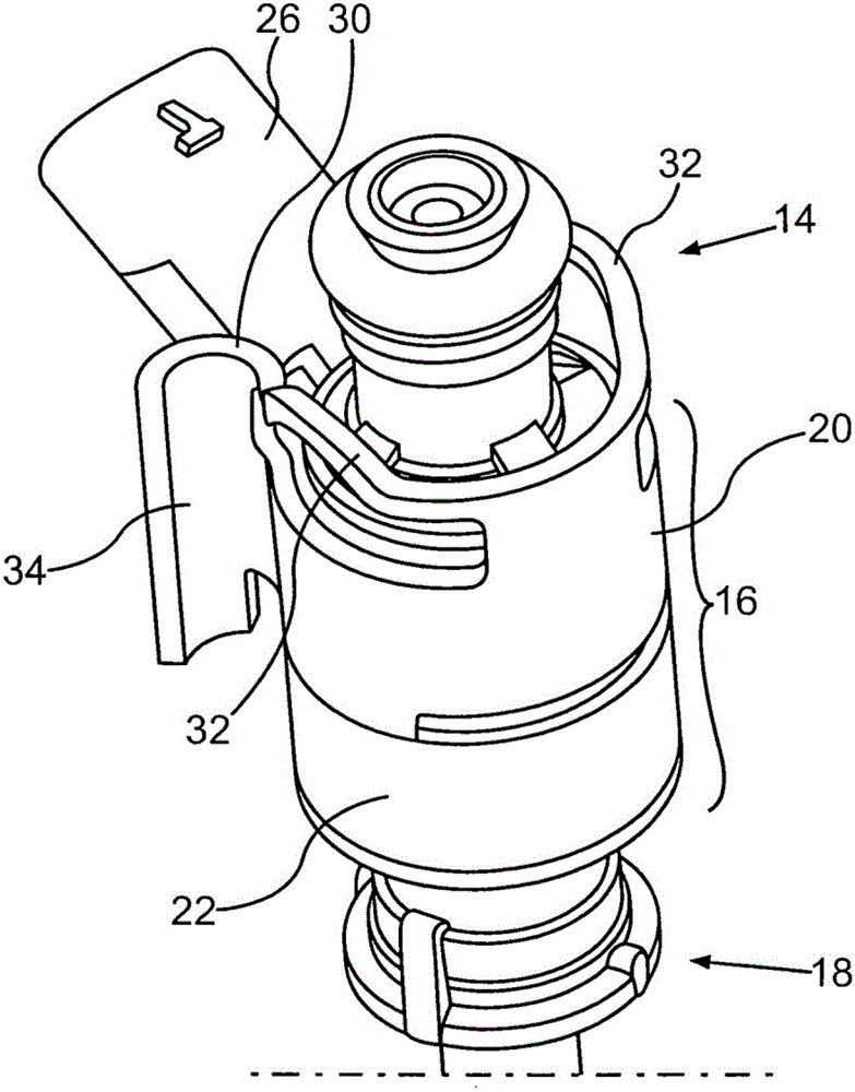
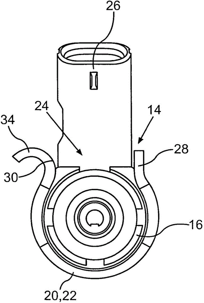
[0024] figure 2 Injection valve 14 , which is shown separately in perspective in FIG. 2 , is inserted with shank region 16 into receiving bore 12 , whereby it protrudes with its nozzle end 18 into the combustion chamber of the engine. Fuel can be injected under high pressure into the combustion chamber via injection valve 14 , which allows better mixture formation in the combustion chamber. In addition, the direct injection of fuel allows different mixing ratios to be produced in different regions of the combustion chamber, whereby it is achieved that the engine is operated at its optimum thermodynamic operating point and thus its efficiency is optimized.

[0025] In order to allow such a locally controlled mixture formation, precise positioning of the injection valve 14 in the receiving bore 12 is required. It is...


PUM


Abstract

The invention relates to an internal combustion engine for a motor vehicle, having at least one cylinder which is assigned an injection valve (14) for the direct injection of fuel into a combustion chamber of the cylinder, wherein the injection valve (14) is received in a receiving opening (12) of a cylinder head (10) of the internal combustion engine and is held in the receiving opening (12) by a supporting element (20), wherein the supporting element (20) is secured in its rotational position by positively locking engagement of a first positively locking element (24) on the injection valve (14) and by positively locking engagement of a second positively locking element (34) on the cylinder head (10). A supporting element (20) of this type ensures particularly satisfactory securing of the rotational position of the injection valve (14). In the case of structural amendments to the cylinder head (10) or to the injection valve (14), merely the supporting element (20) has to be adapted, with the result that amendments of this type can be realized particularly inexpensively.

Description

technical field [0001] The invention relates to an engine according to the preamble of claim 1 having an injection valve for injecting fuel directly into a combustion chamber of a cylinder of the engine. Background technique [0002] Direct injection of fuel into the combustion chamber of an engine is increasingly being used in motor vehicle construction. Compared with injection into the intake manifold or the prechamber of the combustion chamber, direct injection can achieve better mixture formation and thus optimum combustion in the combustion chamber. In addition, direct injection allows the realization of stratified charges, that is, the formation in the combustion chamber of mixtures with different air-fuel ratios in different regions of the combustion chamber. This makes it possible for the engine to be operated in excess oxygen at its thermodynamically optimum operating point, which increases efficiency in particular in the partial load range. This reduces engine co...

Claims


Application Information

Patent Timeline
Patent Type & Authority Applications(China)
IPC IPC(8): F02M61/14
CPCF02M69/04F02M61/14F02M2200/853F02M2200/852
Inventor M·林德纳K·克里普纳
Owner AUDI AG
Learn More