
Construction method of combined prefabricated bridge anti-collision wall

A construction method and anti-collision wall technology, which is applied to bridges, bridge construction, erection/assembly of bridges, etc., can solve problems such as uneven anti-collision walls, difficult fixing of inner formwork and outer formwork, and running of pouring concrete.

Inactive Publication Date: 2013-04-24
GUANGZHOU MUNICIPAL ENG DESIGN & RES INST CO LTD
View PDF7 Cites 11 Cited by
  • Summary
  • Abstract
  • Description
  • Claims
  • Application Information

AI Technical Summary

Problems solved by technology

[0002] As an accessory structure of the bridge, the bridge anti-collision wall is an important safety protection. The bridge anti-collision wall in the prior art is usually constructed by the cast-in-place method. Because the bridge anti-collision wall is usually constructed after the beam body construction is completed. On-site pouring, the bridge anti-collision wall with cast-in-place construction usually needs to install the inner formwork and the outer formwork, and pour concrete between the inner formwork and the outer formwork to form the anti-collision wall. However, the fixing and installation process of the outer formwork is complicated and requires assistance. A lot of installation equipment and a long construction period lead to low construction efficiency, and the inner formwork and outer formwork are not easy to fix, and pouring concrete is prone to mold run-out, which leads to uneven anti-collision walls and affects the appearance of the bridge

Method used


Image

  • Construction method of combined prefabricated bridge anti-collision wall
  • Construction method of combined prefabricated bridge anti-collision wall
  • Construction method of combined prefabricated bridge anti-collision wall

Examples


Embodiment Construction

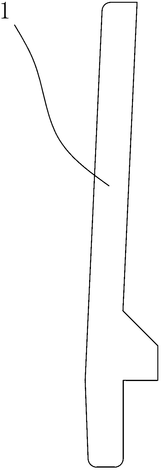
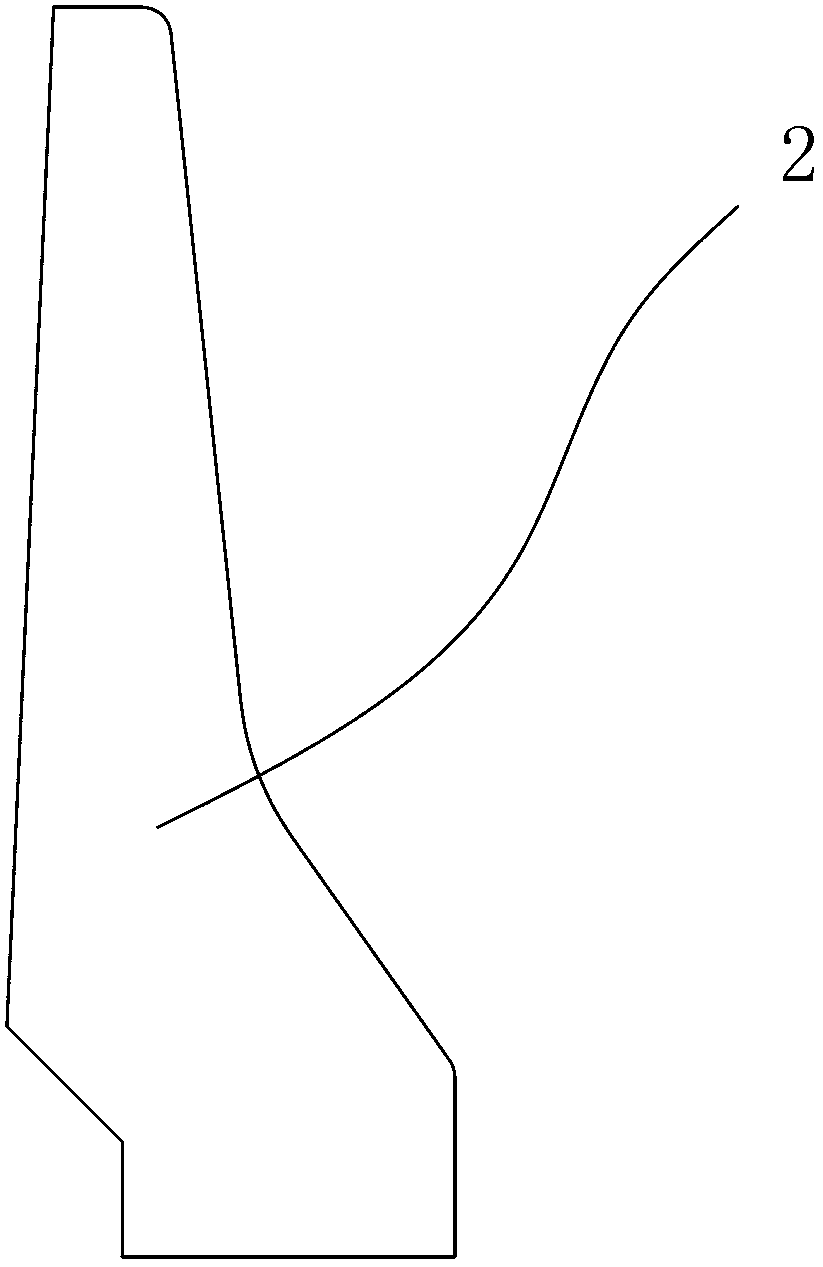
[0018] refer to Figure 1 to Figure 3 , a construction method of a combined bridge prefabricated anti-collision wall of the present invention, comprising the following steps:

[0019] 1) Concrete pouring is used to form the prefabricated outer wall 1 at the predetermined position;

[0020] 2) Fix and install the prefabricated outer wall 1 at the edge of the bridge wing plate 3;

[0021] 3), fixedly install the inner formwork 4 on the bridge wing plate 3 and the prefabricated outer wall 1 at a predetermined distance;

[0022] 4) Concrete is poured between the prefabricated outer wall 1 and the inner formwork 4 to form the inner wall 2 .

[0023] This combined bridge prefabricated anti-collision wall construction method divides the bridge anti-collision wall into two parts, the inner and outer parts, and constructs them separately. The prefabricated outer wall 1 as the outer part can be prefabricated in batches at the prefabricated site, and the prefabricated precast can be po...


PUM


Abstract

The invention discloses a construction method of a combined prefabricated bridge anti-collision wall. The method includes: using concrete to form a prefabricated outer side wall at a preset position by means of pouring; fixedly mounting the prefabricated outer side wall at the edge of a bridge wing plate; fixedly mounting an inner side formwork, with preset distance away from the prefabricated outer side wall, on the bridge wing plate; and pouring concrete between the prefabricated outer side wall and the inner side formwork to form an inner side wall. The inner part and the outer part of the anti-collision wall are constructed separately, the prefabricated outer side wall can be prefabricated in batches on a prefabricating site, and the inner side wall the formed by pouring on site. Due to the fact that the prefabricated outer side wall is used as an outer side formwork for pouring the inner side wall, no extra outer side formwork needs to be fixedly mounted, construction cost is lowered, and the construction procedure of outer side formwork mounting is omitted. In addition, only the inner side wall needs to be formed by pouring on site, workload of on-site concrete pouring is reduced, and engineering construction is accelerated. The construction method is applicable to the technical field of bridge engineering construction.

Description

technical field [0001] The invention relates to the technical field of bridge engineering construction, in particular to a construction method of a bridge anti-collision wall. Background technique [0002] As an accessory structure of the bridge, the bridge anti-collision wall is an important safety protection. The bridge anti-collision wall in the prior art is usually constructed by the cast-in-place method. Because the bridge anti-collision wall is usually constructed after the beam body construction is completed On-site pouring, the bridge anti-collision wall using cast-in-place construction usually needs to install the inner formwork and the outer formwork, and pour concrete between the inner formwork and the outer formwork to form the anti-collision wall. However, the fixing and installation process of the outer formwork is complicated and requires assistance. A lot of installation equipment and a long construction period lead to low construction efficiency, and the inn...

Claims


Application Information

Patent Timeline
IPC IPC(8): E01D21/00
Inventor 刘芳魏立新刘宇晨郭建民
Owner GUANGZHOU MUNICIPAL ENG DESIGN & RES INST CO LTD
Learn More