Mop bucket and mop tray matched with same

A technology for mop buckets and mop discs, which is applied in the direction of cleaning carpets, floors, and cleaning equipment. It can solve the problems of inconvenient operation, complicated deceleration device, and difficult alignment, and achieves easy alignment and positioning, good cleaning effect, and reduced speed. Effect

Inactive Publication Date: 2015-05-27
CIXI BOSHENG PLASTIC PROD
View PDF6 Cites 0 Cited by
  • Summary
  • Abstract
  • Description
  • Claims
  • Application Information

AI Technical Summary

Problems solved by technology

The disadvantages of the existing mops and mop buckets are that it takes a lot of effort to press down and turn the mop rod.
[0003] When the existing mop barrels with speed reduction devices are in use, the height of the speed reduction devices is generally set higher. The reason is that when the mop is pressed, the center of the mop disc needs to be aligned with the center of the speed reduction device. If the height of the speed reduction device If it is too low, the mop pan will all sink into the water contained in the mop bucket. Under the buoyancy of the water, the mop pan will float up, and it will be difficult to align the mop pan after it floats up, which will cause inconvenience in operation.
However, if the height of the deceleration device is set too high, the mop on the mop tray will not be completely soaked, and the cleaning effect will be poor.
[0004] On the other hand, the deceleration device of the existing mop bucket with deceleration device is relatively complicated.

Method used


Image

  • Mop bucket and mop tray matched with same
  • Mop bucket and mop tray matched with same
  • Mop bucket and mop tray matched with same

Examples


Embodiment 2

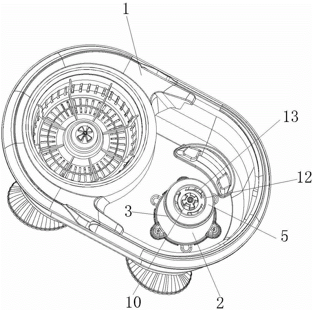
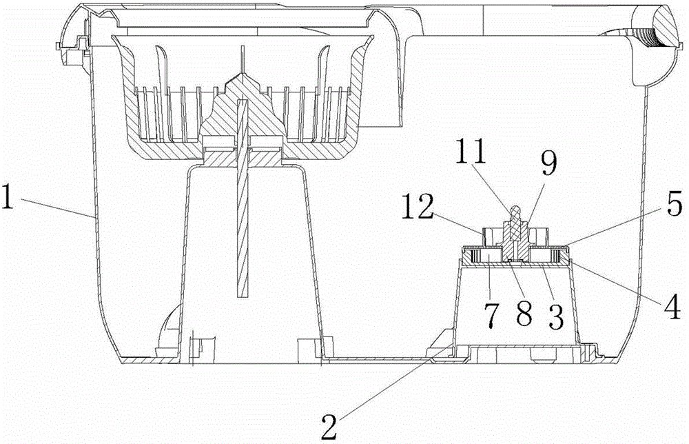
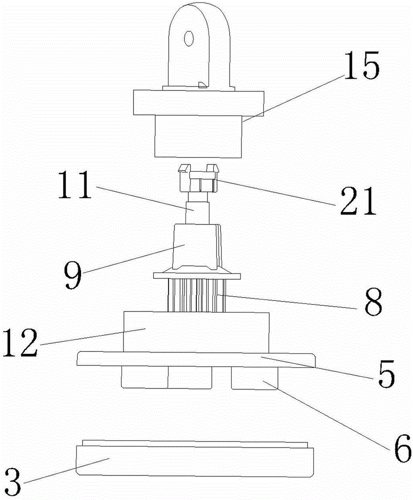
[0049] refer to Figure 1~Figure 5 , Figure 8~Figure 11 , in this embodiment, the axial positioning method of the rotating body 15 is as follows: the center of the disc body 14 is provided with a through opening, the rotating body 15 is provided with a positioning convex ring 26, and the positioning convex ring 26 below The rotating body penetrates into the through opening, and the positioning protrusion ring 26 leans against the upper end surface of the disc body 14 . The positioning convex ring 26 is also covered with a compression cover 27, and the compression cover 27 is also covered with a compression ring 28. The compression ring 28 is provided with a buckle. A bayonet is provided, and the buckle is snapped into the bayonet so as to press the pressing cover 27 on the positioning convex ring 26 . In this embodiment, the back of the disc body 14 is further provided with a shielding ring 29 that shields the bayonet socket.

[0050] The rest of the structure and implemen...


PUM


Abstract

A mop bucket comprises a bucket body and a speed reducer, the speed reducer comprises a base arranged on the bottom surface of the bucket body, a base plate is fixed at the upper end of the base, a rotating disk capable of rotating covers the base plate and is driven to rotate by a planetary gear rotating mechanism, a driving head for power input is arranged on a sun gear of the planetary gear rotating mechanism, and an axial positioning rod is arranged at the center of the driving head. A mop tray matched with the mop bucket comprises s tray body and a rotator, a driving cavity matched with the driving head is arranged on the lower end face of the rotator, and an elastic positioning stop opening matched with a head of the positioning rod is arranged on the bottom surface of the driving cavity. The speed reducer of the mop bucket is simple in structure, and when the mop bucket is matched with the mop tray matched with the same, alignment positioning of the mop tray is convenient, better cleaning effect can be achieved, and use can be more convenient.

Description

technical field [0001] The utility model relates to a mop bucket and a mop plate matched with the mop bucket. Background technique [0002] The hand-pressed rotary mop is more and more popular among home users. When using the hand-pressed rotary mop, press down on the mop, and the mop rod will automatically rotate, thereby driving the mop disc at the bottom of the mop rod to rotate, which is convenient for washing the mop and cloth. And dehydration, washing and dehydration are carried out in the mop bucket. The disadvantage of the existing mop and mop bucket is that it takes a lot of effort to press down and turn the mop rod. Therefore, there has been a mop bucket with a deceleration device, which saves more effort when pressing the mop rod. [0003] When the existing mop barrels with speed reduction devices are in use, the height of the speed reduction devices is generally set higher. The reason is that when the mop is pressed, the center of the mop disc needs to be alig...

Claims


Application Information

Patent Timeline
Patent Type & Authority Patents(China)
IPC IPC(8): A47L13/58A47L13/24
Inventor 黄智勇
Owner CIXI BOSHENG PLASTIC PROD
Why Eureka
Try Eureka