Light source device

A technology of light source device and excitation light source, applied in electric light source, lighting device, projection device, etc., can solve the problems of difficulty and low cost, small thickness of wavelength conversion layer, unsuitable light source conversion layer, etc., and achieve high efficiency.

Active Publication Date: 2013-04-17
USHIO DENKI KK
View PDF12 Cites 16 Cited by
  • Summary
  • Abstract
  • Description
  • Claims
  • Application Information

AI Technical Summary

Problems solved by technology

[0003] However, this slide projector has problems in that it is difficult to achieve low cost because three kinds of solid light emitting devices emitting red, green and blue light are required; amount of light
[0008] However, when the wavelength conversion layer is formed by any of the above-mentioned methods (1) to (3), the thickness of the resulting wavelength conversion layer is small so that a part of the excitation light emitted by the excitation light source is transmitted through the laser conversion layer, so that As a result, it is difficult to emit light with a desired wavelength with high efficiency
[0009] Meanwhile, when the wavelength conversion layer is formed by the above method (4), it is possible to obtain a thicker wavelength conversion layer, but due to the excitation light or the heat caused by the excitation light, the transparent resin constituting the wavelength conversion layer is easily decomposed or deteriorated, so The obtained light source conversion layer is not suitable for use as a wavelength conversion layer of a light source device for slide projectors requiring a large amount of light emission

Method used


Image

  • Light source device
  • Light source device
  • Light source device

Examples


no. 1 approach

[0036] figure 1 It is a schematic diagram showing the light source device of the first embodiment of the present invention. The light source device includes an excitation light source 10 and a plate-shaped wavelength conversion element 20. The excitation light L1 emitted by the excitation light source 10 is applied to one side of the plate-shaped wavelength conversion element 20 ( figure 1 Center left), and the plate-shaped wavelength conversion element 20 is provided in front of the excitation light source 10. Here, the excitation light source 10 is arranged such that the optical axis of the excitation light L1 emitted from the excitation light source 10 to the wavelength conversion element 20 is perpendicular to one side of the wavelength conversion element 20.

[0037] The wavelength conversion element 20 includes a light-transmitting plate 22, and a fluorescent light formed on the light-transmitting plate 22 and containing fluorescence light for receiving excitation light L1 f...

no. 2 approach

[0059] Figure 4 To illustrate a schematic diagram of a light source device according to the second embodiment of the present invention. The light source device includes: an excitation light source 10, and a plate-shaped wavelength conversion element 20. The excitation light L1 emitted by the excitation light source 10 is applied to one side of the plate-shaped wavelength conversion element 20 ( Figure 4 Center left), and the plate-shaped wavelength conversion element 20 is provided in front of the excitation light source 10. The excitation light source 10 is arranged such that the optical axis of the excitation light L1 emitted from the excitation light source 10 to the wavelength conversion element 20 is perpendicular to one side of the wavelength conversion element 20.

[0060] The wavelength conversion element 20 includes a light-transmitting plate 22, and a fluorescent material formed on the light-transmitting plate 22 and containing a fluorescent material that receives exci...

no. 3 approach

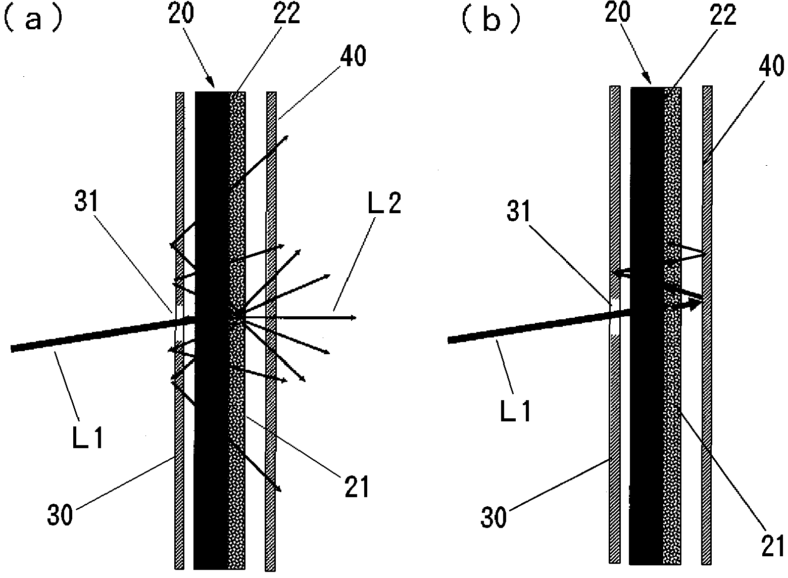
[0071] Image 6 A schematic diagram of a light source device according to a third embodiment of the present invention is shown. The light source device is configured in the same manner as the light source device according to the first embodiment of the present invention, except that the excitation light source 10 is arranged such that the excitation light L1 emitted by the excitation light source 10 is on the side of the wavelength conversion element 20 on the optical axis of the excitation light L1 It is incident on one side of the wavelength conversion element 20 in the oblique direction of the normal of the curved surface.

[0072] In the light source device of this configuration, it is preferable that the optical axis of the excitation light L1 incident on the wavelength conversion element 20 is inclined at an angle of 3 to 10° to the normal to the curved surface of the wavelength conversion element 20. .

[0073] This light source device can exhibit the same effects as the li...


PUM


Abstract

A light source device is provided which converts excitation light to light having a longer wavelength than the excitation light, and which emits the converted light. The light source device can emit light having a required wavelength with a high degree of efficiency. The light source device comprises: an excitation light source which emits the excitation light; a wavelength conversion member which comprises a wavelength conversion layer that is formed on a translucent plate, that receives the excitation light from the excitation light source, and that emits light having a longer wavelength than the excitation light, the excitation light from the excitation light source being input to one face of the wavelength conversion layer; an optical reflecting member which has an excitation light transmission window that transmits the excitation light and that is provided on the side of the one face where the excitation light is input in the wavelength conversion member; and a filter member which is provided on the side of the other face of the wavelength conversion member, reflects the excitation light, and transmits the light having a longer wavelength.

Description

Technical field [0001] The present invention relates to a light source device applicable as a light source of a slide projector. Background technique [0002] Generally, a short arc type high pressure discharge tube is used as the light source of the slide projector. Therefore, a slide projector using a solid-state light-emitting device such as a light-emitting diode, a laser diode, or the like has recently been proposed (refer to Patent Document 1). Compared with the slide projector using a high-pressure discharge tube, the slide projector using the solid-state light-emitting device has the advantage that it does not require a high-voltage power supply, and the solid-state light-emitting device as the light source has a longer life cycle and higher impact resistance. [0003] However, this kind of slide projector has the problem that it is difficult to achieve low cost due to the need to emit three solid-state light-emitting devices that emit red, green and blue light; because th...

Claims


Application Information

Patent Timeline
Patent Type & Authority Applications(China)
IPC IPC(8): F21S2/00F21S8/12G03B21/14
CPCC09K11/646G02B27/142G03B21/204G02B5/0236G02B5/0278G02B5/0294G02B27/106G02B19/0047G02B19/0014H01L33/50
Inventor 芜木清幸堀川好广吉田和弘
Owner USHIO DENKI KK
Why Eureka
Try Eureka