A peeping head control device

A control device and control box technology, which is applied in non-electric variable control, position/direction control, control/regulation system, etc., can solve the problems of large axial size of the motor, low accuracy, and large space occupied by the motor, and achieve the realization of Forward and reverse control, improved accuracy and beautiful appearance

Active Publication Date: 2017-02-08
徐州泰诺仕视觉科技有限公司
View PDF6 Cites 0 Cited by
  • Summary
  • Abstract
  • Description
  • Claims
  • Application Information

AI Technical Summary

Problems solved by technology

[0002] At present, the control device of the domestic peeping head directly pulls the wire drawing through the motor to make the peeping head rotate. Because the diameter of the wire drawing disc is larger, the space occupied vertically to the axial direction becomes larger, and the motor can only be installed horizontally, so that the motor shaft The size of the motor is larger in the vertical direction, which causes the motor to occupy a large space in the vertical direction. Since the horizontal space of the equipment itself has a circuit board, it needs a larger display screen for display in appearance, which makes the overall equipment thick and unsightly; Most of the control devices are pure mechanical devices with complex mechanical mechanism, inconvenient operation and low precision; there are also digital control devices, which use buttons to control the single-chip microcomputer, and the mechanical control device is driven by the single-chip microcomputer to drive the endoscope to rotate. The effect is also not perfect; the most difficult technical problem is that the forward and reverse control of the motor cannot be realized. The traditional technology is to connect the two ends of the potentiometer to the voltage and take the divided voltage value in the center. Such a voltage value can only control the rotation of the motor. One direction, unable to achieve control in two directions

Method used


Image

  • A peeping head control device
  • A peeping head control device
  • A peeping head control device

Examples


Embodiment Construction

[0016] The preferred embodiments of the present invention will be described in detail below in conjunction with the accompanying drawings, so that the advantages and features of the present invention can be more easily understood by those skilled in the art, so as to define the protection scope of the present invention more clearly.

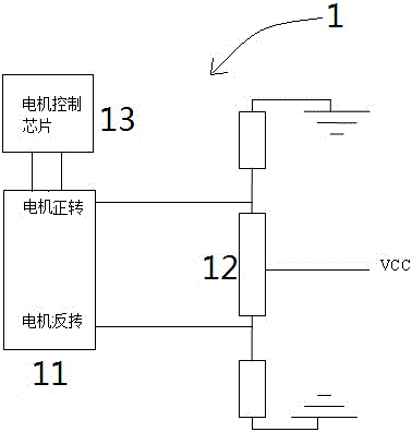
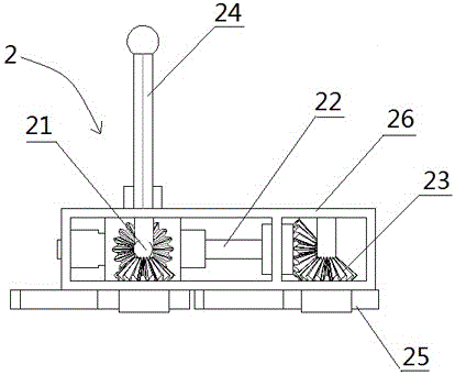
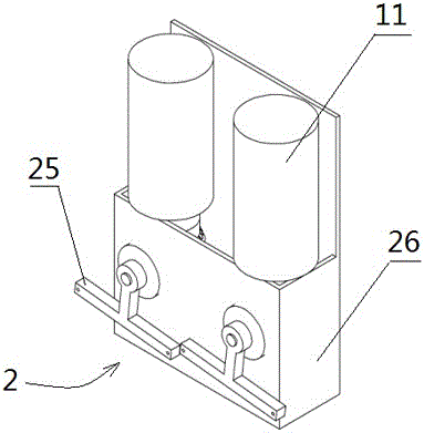
[0017] Such as figure 1 , 2 , 3, the peeping head control device provided by the present invention includes two identical control circuits 1 and the rotation guide mechanism 2 that adjusts the control circuit 1, and the rotation guide mechanism 2 includes A worm screw 21, B worm screw screw 22, bevel gear 23. A hand handle 24, a wire drawing disc 25 and a control box 26 are formed. The A worm 21 and the B worm 22 are vertically installed in the control box 26, and the B worm 22 at its intersection is set as an arc; the hand crank The handle 24 is installed vertically on the outer surface of the control box 26, and is movably connected with the A...


PUM


Abstract

The invention provides a probe control device which comprises two same control circuits and a rotation guide mechanism, wherein the rotation guide mechanism is used for adjusting the control circuits, each control circuit is composed of a motor, a potentiometer and a chip, both ends of the potentiometer are connected with pull-down resistors and connected with the ground, the center of the potentiometer is connected with a high level, and the both ends of the potentiometer are in input control connection with two direction levels of the motor controlled chip. According to the probe control device, through the two same unique control circuits and the rotation guide mechanism used for adjusting the control circuits, the size of the control device in the longitudinal space is reduced, the whole device is integrally thinner, the appearance is more attractive, the positive-negative rotation control over motors and the accurate control over a mechanical device by the control device are realized, and the device has the advantages of attractive appearance, convenience in operation and precision improvement.

Description

technical field [0001] The invention relates to the field of control devices, in particular to a peeking head control device. Background technique [0002] At present, the control device of the domestic peeping head directly pulls the wire drawing through the motor to make the peeping head rotate. Because the diameter of the wire drawing disc is larger, the space occupied vertically to the axial direction becomes larger, and the motor can only be installed horizontally, so that the motor shaft The size of the motor is larger in the vertical direction, which causes the motor to occupy a large space in the vertical direction. Since the horizontal space of the equipment itself has a circuit board, it needs a larger display screen for display in appearance, which makes the overall equipment thick and unsightly; Most of the control devices are pure mechanical devices with complex mechanical mechanism, inconvenient operation and low precision; there are also digital control device...

Claims


Application Information

Patent Timeline
Patent Type & Authority Patents(China)
IPC IPC(8): G05D3/00
Inventor 吴琛唐慧超霍轶杰
Owner 徐州泰诺仕视觉科技有限公司
Why Eureka
Try Eureka