
Optical fiber distribution box

An optical fiber distribution box and optical fiber adapter technology, applied in the direction of fiber mechanical structure, etc., can solve the problems of unreasonable space layout, inability to take into account power communication equipment and communication operators, etc., and achieve the effect of long service life and cost reduction

Inactive Publication Date: 2013-04-17
STATE GRID SHANDONG ELECTRIC POWER +1
View PDF2 Cites 2 Cited by
  • Summary
  • Abstract
  • Description
  • Claims
  • Application Information

AI Technical Summary

Problems solved by technology

[0008] The technical problem to be solved by the present invention is that due to the unreasonable spatial layout of the optical fiber distribution box in the prior art, it cannot take into account the installation needs of power communication equipment and communication operators' three-in-one equipment, and then provide a kind of equipment that can simultaneously take into account the telecommunications business. Optical fiber distribution box for access and electrical information collection

Method used


Image

  • Optical fiber distribution box
  • Optical fiber distribution box
  • Optical fiber distribution box

Examples


Embodiment 1

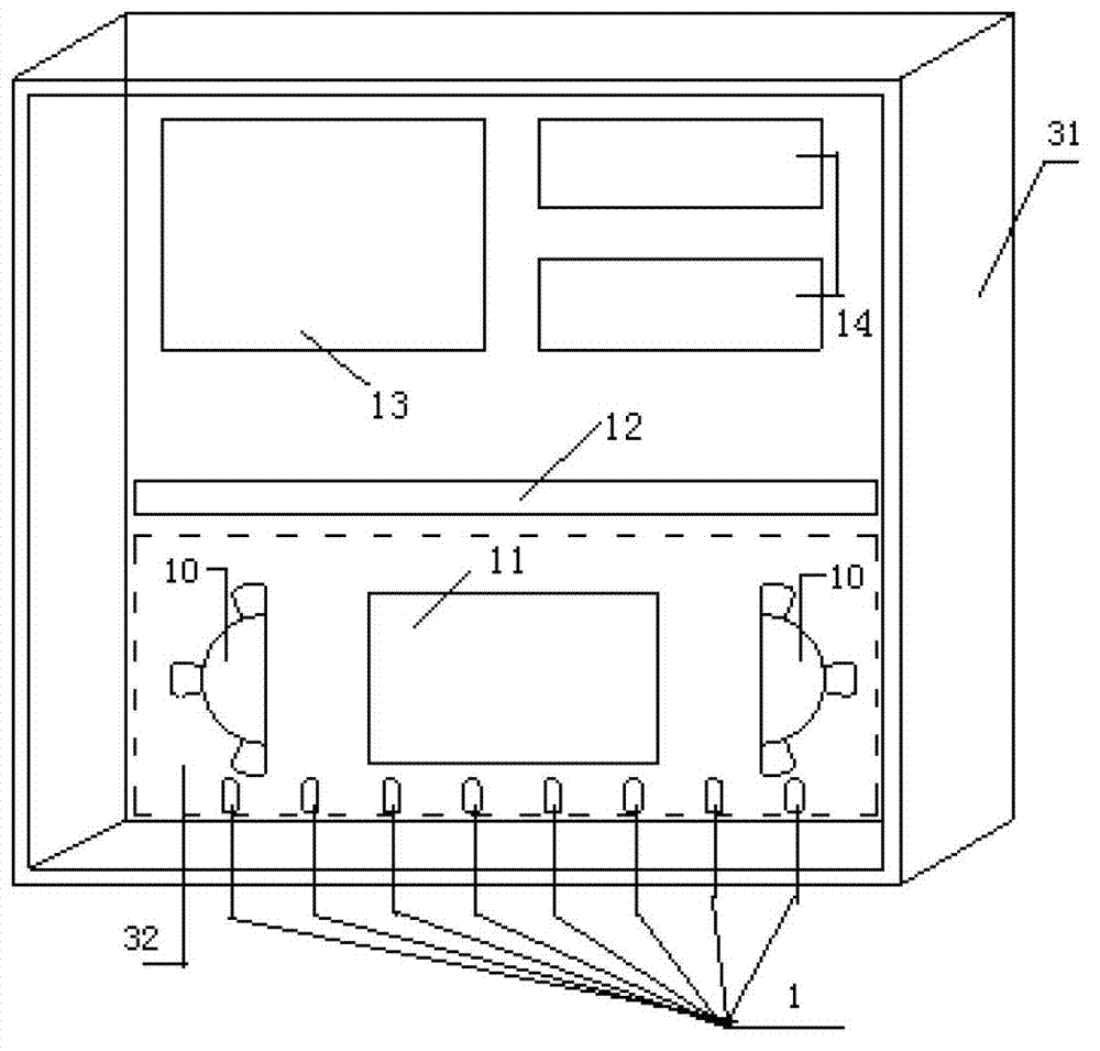
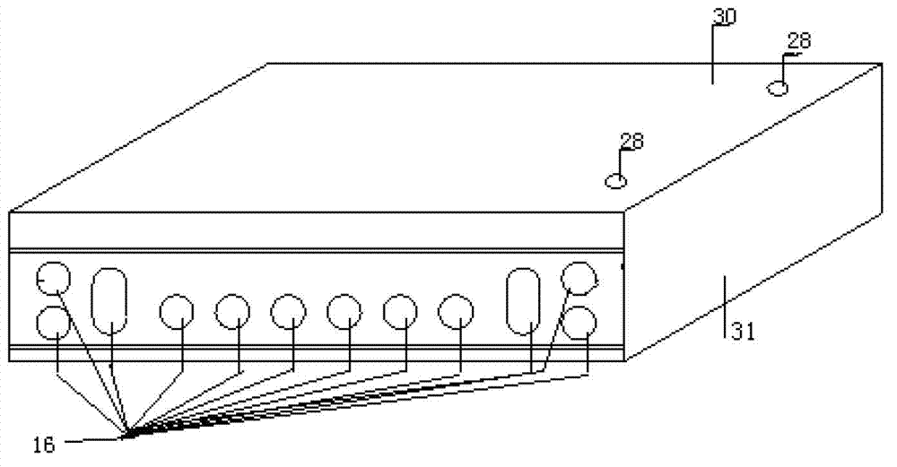
[0028] This embodiment provides an optical fiber distribution box, including a box body 31 and a cover plate 30, the cover plate 30 can be fastened to the box body 31 to form a cavity, figure 1 A schematic diagram of its internal structure is given. As shown in the figure, an optical fiber adapter 12 is arranged in the box body 31. Preferably, the optical fiber adapter 12 is a 72-core optical fiber distribution device. One side of the optical fiber adapter 12 in the box body 31 is provided with an optical fiber fusion splicing tray 32, and the direct melting plate 11 and the pair of remaining optical cables on both sides of the direct melting plate 11 are arranged on the optical fiber fusion splicing tray 32. The fiber winding reel 10 for disk storage; the optical cable enters the box body 31 through the wire inlet 16 and is welded with the distribution pigtail on the direct melting plate 11, and the distribution pigtail is connected to the jumper through the optical fiber adap...

Embodiment 2

[0031] This embodiment makes the following improvements on the basis of Embodiment 1. The optical fiber splicing tray 32 is detachably arranged on the bottom plate of the box body 31 through a fixing member, and the fixing member can be selected as bolts and nuts or other type of fixture. The side of the optical fiber fusion splicing tray 32 close to the wire inlet 16 is provided with a holder 1 for fixing the optical cable, such as figure 1 As shown, the deck 1 can be selected to be 8.

[0032] In this embodiment, the optical fiber fusion splicing tray 32 is detachably arranged on the bottom plate of the box body 31, so that the optical fiber fusion splicing position can be flexibly selected according to the actual situation. If necessary, the optical fiber fusion splicing tray 32 can be removed to select the most fiber-saving position. Fusion splicing can save at least 1 to 1.5 meters of optical fiber, saving costs.

[0033] In addition, in order to effectively prevent win...


PUM


Abstract

The invention discloses an optical fiber distribution box, which comprises a box body and a cover plate, wherein the cover plate can be buckled on the box body to form a cavity, an optical adapter is arranged in the box body, one side of the optical fiber adapter is provided with an optical fiber fusion splicing disc, a direct fusion plate and a fiber winding disc are arranged on the optical fiber fusion splicing disc, the fiber winding disc is arranged at two sides of the direct fusion plate and is used for winding and storing remaining optical cables, optical cables enter the box body through a wire inlet and are in fusion splicing with distribution tail fibers on the direct fusion splicing plate, the distribution tail fibers are connected with jumper wire tail fibers through the optical fiber adapter, the jumper wire tail fibers are output of the box body through a wire outlet, and the other side of the optical fiber adapter is provided with an XPON optical fiber access device and an optical divider. The optical fiber distribution box has the advantages that partial equipment of operators and power communication are integrated arranged in the optical fiber distribution box, and the communication equipment installation equipments required by the three-in-one network of the power communication and operation enterprises are taken into considerations. The telecommunication service access can be realized, and the optical fiber distribution box is also suitable for the fiber-to-the-home engineering in small high-rise and high-rise residential areas.

Description

technical field [0001] The invention relates to an optical fiber distribution box for OPLC (Optical Fiber Composite Low-voltage Cable). Background technique [0002] In recent years, with the development of smart grids, the State Grid Corporation of China has proposed the concept of "four-network integration", that is, the organic integration of power grids, telecommunication networks, broadcasting networks, and the Internet. Since OPLC combines the functions of optical fiber communication and power transmission, compared with single-function transmission cables, it has the characteristics of high reliability data transmission, low price, convenient connection, and the integration of optical cables and power lines without secondary wiring. OPLC realizes fiber-to-the-home, solves the problem of repeated investment in the construction of optical cable lines, and reduces "black pollution". As an important access device connecting users and the network, optical fiber distributi...

Claims


Application Information

Patent Timeline
Patent Type & Authority Applications(China)
IPC IPC(8): G02B6/44
Inventor 周建波王泽众毕晓芬
Owner STATE GRID SHANDONG ELECTRIC POWER
Learn More