Hot air furnace drying box

A technology of hot blast stove and drying oven, which is applied in the direction of drying gas arrangement, local stirring dryer, static material dryer, etc. Speed, eliminate moisture, good effect of air supply

Inactive Publication Date: 2013-04-17
赵立地
View PDF7 Cites 3 Cited by
  • Summary
  • Abstract
  • Description
  • Claims
  • Application Information

AI Technical Summary

Problems solved by technology

The hot blast stove is a square box with closed sides and an opening at the top. The combustion furnace is placed below the square box. An axial flow fan is installed above the combustion furnace. An air inlet is provided under the partition adjacent to the left and right drying boxes. The air is forced to flow under the action of the fan. After being heated by the combustion furnace, the air enters the bottom of the left and right drying boxes from the above-mentioned air inlet, passes through the material layer in the drying box, and is discharged. The disadvantage of this technology is that it is different from the drying box. The temperature difference between the upper and lower sides is large, the wind resistance of the hot air is large, and the flow rate is slow. The phenomenon that the material in the middle is cooked, the drying speed is slow, the drying cycle is long, the quality of the dried material is poor, and the energy consumption is high.

Method used


Image

  • Hot air furnace drying box

Examples


Embodiment Construction

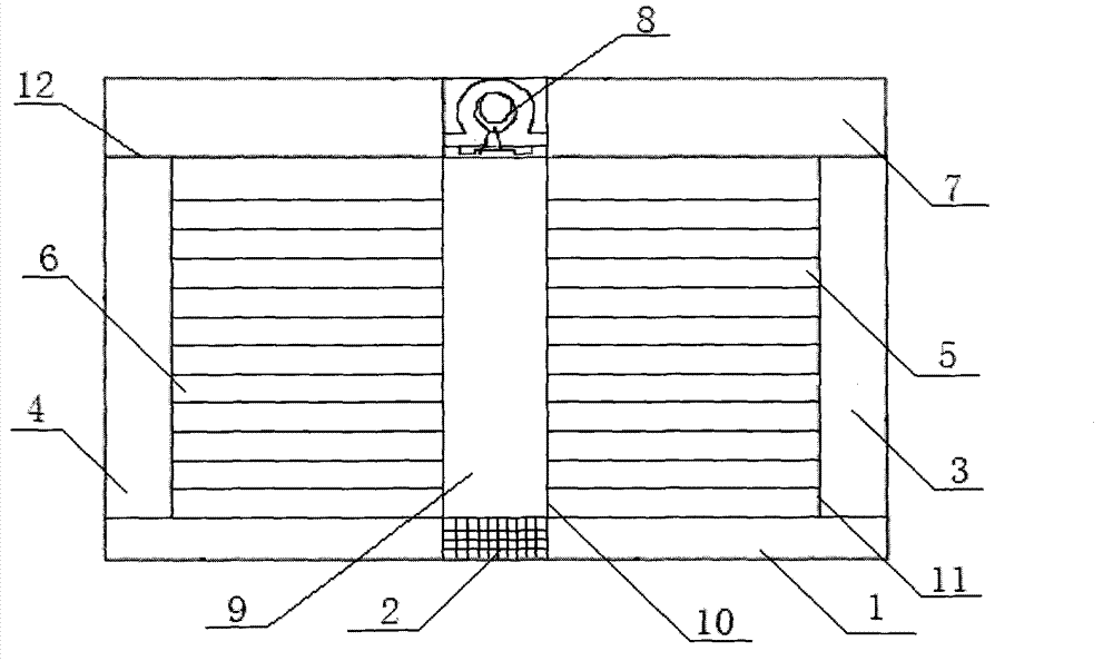
[0014] As shown in the drawings, the present invention includes a base 1, a hot blast stove 2 arranged in the center of the base 1, a central air supply chamber 9 communicating with the hot blast stove 2, a hot blast inlet 10 and a central air supply chamber 9 arranged at the left and right ends of the central air supply chamber 9 The left ventilating and drying chamber 6 and the right ventilating and drying chamber 5 communicated with the air supply chamber 9, the left ventilating pipe 4 and the right ventilating pipe 3 arranged at the ends of the left ventilating and drying chamber 6 and the right ventilating and drying chamber 5 respectively, and the left ventilating pipe 3 arranged at the ends of the left ventilating and drying chamber 4 and the top ventilation pipe 7 on the upper end of the right ventilation pipe 3 and the centrifugal fan 8 arranged on the top of the central air supply chamber 9, the left ventilation drying chamber 6 and the right ventilation drying chamber...


PUM


Abstract

The invention relates to a hot air furnace drying box. The hot air furnace drying box comprises a base, a hot air furnace arranged at the center of the base, a central air supply cavity communicated with the hot air furnace, a left ventilating and drying cavity, a right ventilating and drying cavity, a left ventilating tube, a right ventilating tube, top ventilating tubes arranged at the upper ends of the left ventilating tube and the right ventilating tube, and a centrifugal fan arranged at the upper portion of the central air supply cavity, wherein the left ventilating and drying cavity and the right ventilating and drying cavity are arranged at the left end and the right end of the central air supply cavity and communicated with the central air supply cavity through hot air inlets, and the left ventilating tube and the right ventilating tube are respectively arranged the end portions of the left ventilating and drying cavity and the right ventilating and drying cavity. The left ventilating and drying cavity and the right ventilating and drying cavity are respectively communicated with the left ventilating tube and the right ventilating tube through hot air outlets. The hot air furnace drying box is balanced in material drying and good in drying effect.

Description

technical field [0001] The invention relates to a hot blast stove drying box. Background technique [0002] At present, the known drying equipment for agricultural and sideline products has a structure that drying boxes are arranged on the left and right sides of the hot blast stove. The hot blast stove is a square box with closed sides and an opening at the top. The combustion furnace is placed below the square box. An axial flow fan is installed above the combustion furnace. An air inlet is provided under the partition adjacent to the left and right drying boxes. The air is forced to flow under the action of the fan. After being heated by the combustion furnace, the air enters the bottom of the left and right drying boxes from the above-mentioned air inlet, passes through the material layer in the drying box, and is discharged. The disadvantage of this technology is that it is different from the drying box. The temperature difference between the upper and lower sides is l...

Claims


Application Information

Patent Timeline
Patent Type & Authority Applications(China)
IPC IPC(8): F26B9/06F26B21/00
Inventor 赵立地
Owner 赵立地
Why Eureka
Try Eureka