
Estrus detection device and estrus detection system

A technology of estrus detection and communication device, which is applied in the field of estrus detection device and estrus detection system, and can solve the problems of expensive equipment and the like

Inactive Publication Date: 2014-12-24
PANASONIC CORP
View PDF7 Cites 0 Cited by
  • Summary
  • Abstract
  • Description
  • Claims
  • Application Information

AI Technical Summary

Problems solved by technology

[0007] However, the conventional detection device needs a large-scale system including the statistical device 101 to judge the estrus state of the cow
Therefore, the equipment becomes expensive

Method used


Image

  • Estrus detection device and estrus detection system
  • Estrus detection device and estrus detection system
  • Estrus detection device and estrus detection system

Examples


Embodiment approach 1

[0025] Figure 1A , Figure 1B It is an external view showing the estrus detection device of the first embodiment. In the figure, the estrus detection device 1 has a belt 20 on the lower side of the housing 2. Such as figure 2 As shown, the housing 2 is attached to the neck of a cow as a livestock using a belt 20. The livestock to which the estrus detection device 1 is installed may also be pigs, horses, or the like.

[0026] Next, use Figure 3 to Figure 6 The internal structure of the housing 2 will be described.

[0027] The display board 3, the control board 4, and the power supply 5 are housed in the housing 2. A display unit 30 is provided on the display substrate 3. The control board 4 is provided with a three-axis acceleration sensor 40 as an activity sensor, a signal processing unit 41, a temporary storage unit 42, a storage unit 43, and an estrus determination unit 44.

[0028] The activity sensor detects the activity of livestock. As the activity sensor, various acce...

Embodiment approach 2

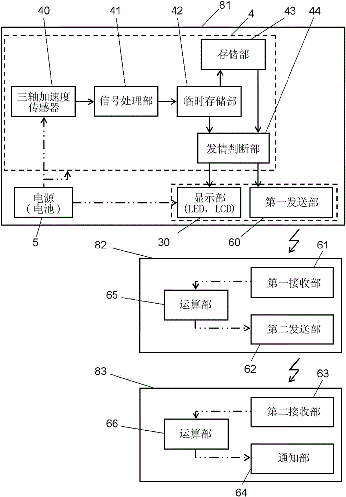
[0062] Figure 8 It is the block diagram of the estrus detection system. In the figure, the same reference numerals are attached to the same parts as in the first embodiment, and the description is cited.

[0063] The estrus detection system has an estrus detection device 81, a communication device 82, and a notification device 83. The estrus detection device 81 of the second embodiment includes the first transmission unit 60 in the estrus detection device 1 described in the first embodiment. The estrus determination unit 44 transmits to the first transmission unit 60 that the cow is in heat. The first transmitting unit 60 transmits a first estrus state signal indicating that the cow is in the estrus state to the first receiving unit 61 of the communication device 82.

[0064] The first estrus state signal received by the first receiving unit 61 is sent to the second transmitting unit 62 via the computing unit 65. The second transmitting unit 62 transmits to the second receiving...


PUM


Abstract

An estrus detection device is composed of a resin case (2) and a belt (20) to be attached to a livestock animal. The case (2) contains a triaxial acceleration sensor (40) as an activity sensor for detecting the motion of the animal; a signal processing unit (41) for converting the output of the triaxial acceleration sensor (40) to the amount of activity; a temporary storage unit (42) for storing the output of the signal processing unit (41) as the present amount of activity; a storage unit (43) for storing, as the past amount of activity for a past predetermined time period, the amount of activity stored so far in the temporary storage unit (42); an estrus determination unit (44) for determining whether the animal is in estrus or not based on the past amount of activity and the present amount of activity; and a display part (30) for showing that the animal in in estrus when the estrus determination unit (44) has determined that the animal in in estrus.

Description

Technical field [0001] The invention relates to a device for detecting the estrus period of domestic animals, especially cattle. Background technique [0002] In order to efficiently increase calf production, it is important to detect the estrus state of the cow, especially the moment when the estrus begins. As a device for detecting the state of estrus, there is a device using a pedometer (refer to Patent Document 1). [0003] Install a pedometer on the cow as the object. Divide a day into multiple time periods. The detection device extracts the number of steps counted by the pedometer according to each time period. The detection device compares the counted number of steps with the number of steps in the same time period in the past n days. The estrus state is detected based on the comparison result. [0004] use Picture 9 Let's explain in detail. The detection device for the estrus state includes a statistics device 101 and at least one pedometer 102. The statistics device 1...

Claims


Application Information

Patent Timeline
Patent Type & Authority Patents(China)
IPC IPC(8): A01K67/02
CPCA01K29/005A61D17/002
Inventor 则武圭辅水谷义辉
Owner PANASONIC CORP
Learn More