Comb spectrum generation system based on cyclic frequency shift pattern and application method thereof
A technology for generating system and comb spectrum, applied in the field of optical communication, can solve the problems of low work efficiency, large RF driving power, expensive device, etc., to improve flatness and stability, reduce system complexity, and achieve superior performance Effect
- Summary
- Abstract
- Description
- Claims
- Application Information
AI Technical Summary
Problems solved by technology
Method used
Image
Examples
Embodiment 1
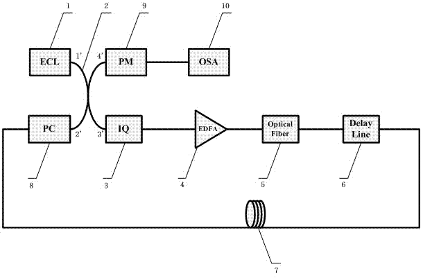
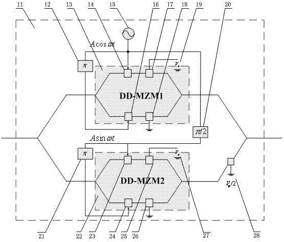
[0013] see Figure 1~Figure 2 , the comb spectrum generation system based on cyclic frequency shifting method: the output port of an external cavity semiconductor laser ECL (1) is connected to the first input port (1') of a 3dB coupler (2), and the loop optical modulator The modulated signal is connected to the second input port (2') of the 3dB coupler (2) through a polarization controller PC (8), and the first output port (4') of the 3dB coupler (2) A phase modulator PM (9) is connected to an optical spectrum analyzer OSA (10), and the second output port (3') of the 3dB coupler (2) is connected to an IQ modulator (3), and the IQ modulator The output port of the device (3) is connected to an erbium-doped fiber amplifier EDFA (4), and the output port of the erbium-doped fiber amplifier EDFA (4) is connected to an optical filter (5), and the output port of the optical filter (5) is connected to a An optically adjustable delay line (6), the output port of the optically adjustabl...
Embodiment 2
[0015] see Figure 1~Figure 2 , the application method of the comb spectrum generator based on the cyclic frequency shifting method adopts the above-mentioned system for operation. The external cavity semiconductor laser ECL (1) outputs the seed light to the first input port (1') of the 3dB coupler (2), and the second output port (3') of the 3dB coupler (2) is connected to the input of the IQ modulator (3) port, the IQ modulator (3) passes through the erbium-doped fiber amplifier EDFA (4), optical filter (5), optical adjustable delay line (6), loop fiber link (7) and polarization The controller PC (8) is connected to the second input port (2') of the 3dB coupler (2), and the first output port (4') of the 3dB coupler (2) is connected to the optical frequency spectrum analysis through the phase modulator PM (9) Instrument OSA (10). Input the cosine radio frequency signal, the reverse cosine radio frequency signal, the sine radio frequency signal of the same frequency an...
PUM
 Abstract
Description
Claims
Application Information
 - R&D
- Intellectual Property
- Life Sciences
- Materials
- Tech Scout
- Unparalleled Data Quality
- Higher Quality Content
- 60% Fewer Hallucinations
Browse by: Latest US Patents, China's latest patents, Technical Efficacy Thesaurus, Application Domain, Technology Topic, Popular Technical Reports.
© 2025 PatSnap. All rights reserved.Legal|Privacy policy|Modern Slavery Act Transparency Statement|Sitemap|About US| Contact US: help@patsnap.com


