
Liquid crystal display device

A liquid crystal display device and array substrate technology, which is applied in nonlinear optics, instruments, optics, etc., can solve the problems of reduced light transmittance of display devices, low light utilization rate of backlight source, short service life, etc., and achieves improved light transmittance. The effect of increasing the light utilization rate and reducing the power consumption

Active Publication Date: 2013-04-10
BOE TECH GRP CO LTD +1
View PDF5 Cites 32 Cited by
  • Summary
  • Abstract
  • Description
  • Claims
  • Application Information

AI Technical Summary

Problems solved by technology

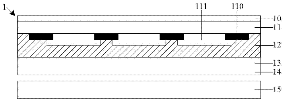
In the prior art, the structure of the liquid crystal display device 1 includes: an upper polarizer 10, a color filter substrate 11 provided with an RGB three primary color filter layer 111 and a black matrix 110, a liquid crystal layer 12, an array substrate 13, a lower polarizer 14 and The backlight source 15, however, because the black matrix 110 has a certain area, therefore, among the light rays entering the color filter substrate 11 from the backlight source 15, only the light rays facing the area of ​​the RGB three-primary color filter layer 111 can pass through the color filter substrate and reach people's eyes, other light is all absorbed by the black matrix 110, which reduces the light transmittance of the liquid crystal display device, resulting in a particularly low light utilization efficiency of the backlight
[0004] To improve the light transmittance of the liquid crystal display device, it is necessary to increase the luminous brightness of the backlight source. The higher the luminous brightness of the backlight source, the greater the power consumption of the corresponding light source LED (Light Emitting Diode, Light Emitting Diode). shorter lifespan

Method used


Image

  • Liquid crystal display device
  • Liquid crystal display device
  • Liquid crystal display device

Examples


Embodiment Construction

[0023] The following will clearly and completely describe the technical solutions in the embodiments of the present invention with reference to the accompanying drawings in the embodiments of the present invention. Obviously, the described embodiments are only some, not all, embodiments of the present invention. Based on the embodiments of the present invention, all other embodiments obtained by persons of ordinary skill in the art without making creative efforts belong to the protection scope of the present invention.

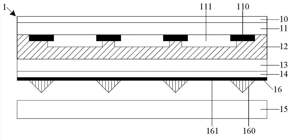
[0024] Such as figure 2 As shown, the embodiment of the present invention provides a liquid crystal display device 1, including an array substrate 13, a color filter substrate 11 having a black matrix 110 and a color filter layer 111 arranged opposite to the array substrate 13, and arranged between the color filter substrate 11 and the color filter substrate 11. The liquid crystal layer 12 between the array substrates 13, the enhancement film 16 disposed unde...


PUM


Abstract

The embodiment of the invention provides a liquid crystal display device, which relates to the technical field of liquid crystal display and can be used for increasing the light transmission rate of the liquid crystal display device, so as to increase the light utilization ratio of a backlight source, lower the power consumption of an LED (Light-Emitting Diode) and prolong the service life of the LED. The liquid crystal display device comprises an array substrate, a color film substrate, a liquid crystal layer and a light enhancing film, wherein the color film substrate is arranged opposite to the array substrate, and is provided with a black matrix and a color filter layer; the liquid crystal layer is arranged between the color film substrate and the array substrate; and the light enhancing film is arranged below the array substrate, and comprises a reflecting part which is arranged corresponding to the black matrix.

Description

technical field [0001] The invention relates to the technical field of liquid crystal display, in particular to a liquid crystal display device. Background technique [0002] With the continuous development of liquid crystal display technology, more and more people pay attention to color liquid crystal display devices. Compared with the previous black and white display devices, color liquid crystal display devices can provide people with rich colors, so that people can get more information. [0003] In the liquid crystal display device, the liquid crystal itself does not emit light, and the light emitted from the backlight passes through the liquid crystal and passes through the RGB (Red Green Blue, red, green, blue) three primary color filter layers of the color film substrate to display different colors. image. In the prior art, the structure of the liquid crystal display device 1 includes: an upper polarizer 10, a color filter substrate 11 provided with an RGB three pri...

Claims


Application Information

Patent Timeline
Patent Type & Authority Applications(China)
IPC IPC(8): G02F1/1335G02F1/13357
Inventor 乔中莲杨东升马国恒郑卫新
Owner BOE TECH GRP CO LTD
Learn More