
Tilt correction system based on beacon light detection

A technology of tilt correction and beacon light, which is applied in the field of telescope control, can solve problems such as reduced image detection and recognition capabilities, insufficient control bandwidth, and complex correction systems, so as to improve detection accuracy and imaging quality, eliminate shaft shaking, and engineering achieve easy results

Active Publication Date: 2015-02-18
INST OF OPTICS & ELECTRONICS - CHINESE ACAD OF SCI
View PDF2 Cites 0 Cited by
  • Summary
  • Abstract
  • Description
  • Claims
  • Application Information

AI Technical Summary

Problems solved by technology

The main reason affecting the performance of the tilt correction system is that the frame frequency of the CCD detection system is low, so that the control bandwidth of the tilt correction is not enough to eliminate higher frequency disturbances (such as wind torque, shaft shaking, etc.)
Although the CCD detection system with high frame rate increases the control bandwidth, it reduces the image detection and recognition capabilities; secondly, in order to make the tilt correction system work stably and reliably, generally multiple CCD detection systems are placed in the same optical path, which will Complicates the correction system

Method used


Image

  • Tilt correction system based on beacon light detection
  • Tilt correction system based on beacon light detection
  • Tilt correction system based on beacon light detection

Examples


Embodiment 1

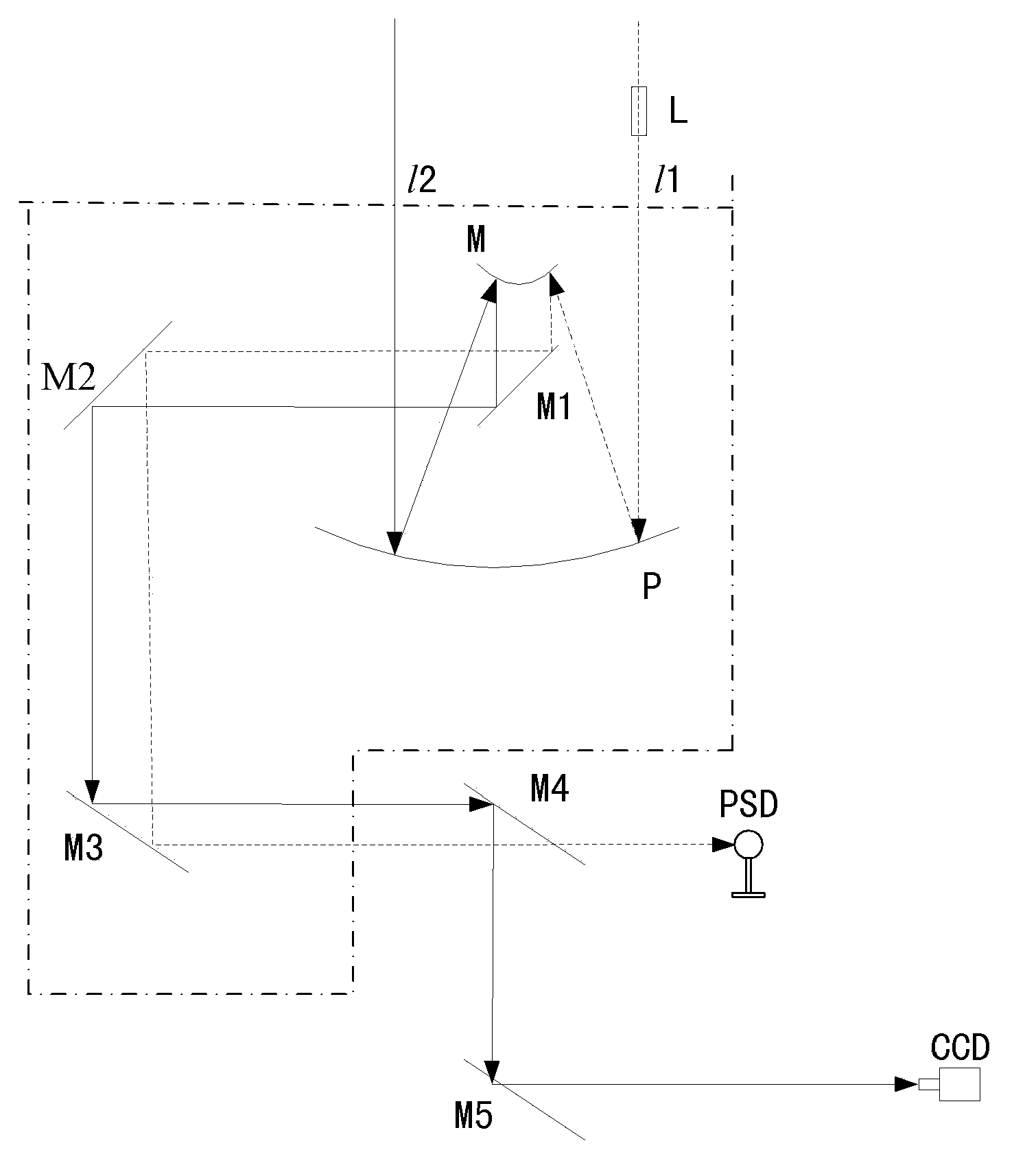
[0028] Embodiment 1: The optical path of the telescope Kuder includes a primary mirror P, a secondary mirror M, a first relay mirror M1, a second relay mirror M2, and a third relay mirror M3, wherein,

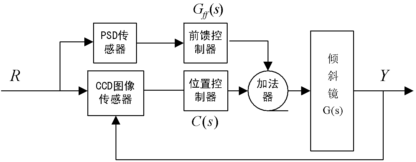
[0029] The reflective surfaces of the beam splitter M4 and the tilting mirror M5 are opposite and placed parallel to each other; the PSD sensor is located behind the beam splitter M4; the CCD image sensor is placed behind the tilting mirror M5; the beacon light source L is installed on the lens barrel of the telescope, and the beacon light source L With the rotation of the telescope lens barrel, the beacon light l1 emitted by the beacon light source L passes through the primary mirror P, the secondary mirror M, the relay mirrors M1, M2 and the beam splitter M3 in the optical path of the telescope Coud, and then passes through the beam splitter M4, Arrive at the PSD sensor; after the target light l2 passes through the optical path of the telescope Kuder, the primary mirror P, the...


PUM


Abstract

The invention discloses a tilt correction system based on beacon light detection for eliminating a tracking error of a telescope and improving image stabilization precision, and in particular relates to the telescope, a quick tilting mirror, a beacon light source, a CCD (Charge-Coupled Device) image sensor, a PSD (Phase-Sensitive Detector) and a light splitter. The beacon light source is guided in from a lens cone of the telescope; and through a Kurdish light path in the telescope, beacon light is reflected and projected to a PSD sensor. The position information of an observed object provided by the CCD image sensor is input as a closed loop of the quick tilting mirror; the PSD sensor provides the position information of the beacon light as feedforward control quantity; and the position information is guided in the quick tilting mirror so as to realize the correction system. The system facilitates engineering implementation, and has excellent practicability.

Description

technical field [0001] The invention relates to the field of telescope control, in particular to a tilt correction system for beacon light detection, which is mainly used for eliminating the tracking error of the tracking telescope and improving the image stabilization precision. Background technique [0002] The telescope usually adopts a compound axis control system based on fast tilt correction to further eliminate the tracking error of the telescope and improve the observation clarity of the image. The main reason affecting the performance of the tilt correction system is that the frame frequency of the CCD detection system is low, which makes the control bandwidth of the tilt correction insufficient to eliminate higher frequency disturbances (such as wind torque, shaft shaking, etc.). Although the CCD detection system with high frame rate increases the control bandwidth, it reduces the image detection and recognition capabilities; secondly, in order to make the tilt cor...

Claims


Application Information

Patent Timeline
Patent Type & Authority Patents(China)
IPC IPC(8): G02B23/00G02B23/12G02B26/08
Inventor 唐涛钟代军刘儒贞包启亮任戈
Owner INST OF OPTICS & ELECTRONICS - CHINESE ACAD OF SCI
Learn More