Blast type combustor

A burner and air blast technology, applied in the direction of burners, gas fuel burners, combustion methods, etc., can solve problems affecting combustion conditions, difficult secondary air uniformity, difficult high energy, high efficiency, etc., to achieve full combustion , controllable air volume and high combustion efficiency

Active Publication Date: 2013-04-10
VATTI CORP LTD
View PDF8 Cites 18 Cited by
  • Summary
  • Abstract
  • Description
  • Claims
  • Application Information

AI Technical Summary

Problems solved by technology

[0002] At present, there are all kinds of blast stove burners on the market, but in terms of structure, they are nothing more than primary air blast burners, secondary air blast burners, primary air, and secondary air burners. At the same time blast burner; and the secondary air blast burner on the market, the secondary air is naturally diffused and shunted after reaching the surface of the fire cover through the channel, which is limited to the layout of the fire hole, the structure of the air distribution cavity, and the shape of the fire cover , it is difficult to achieve the uniformity of secondary air distribution, which affects the combustion conditions, especially for burners with multiple rows of fire holes, it is difficult to achieve high energy and high efficiency

Method used


Image

  • Blast type combustor
  • Blast type combustor
  • Blast type combustor

Examples


Embodiment 1

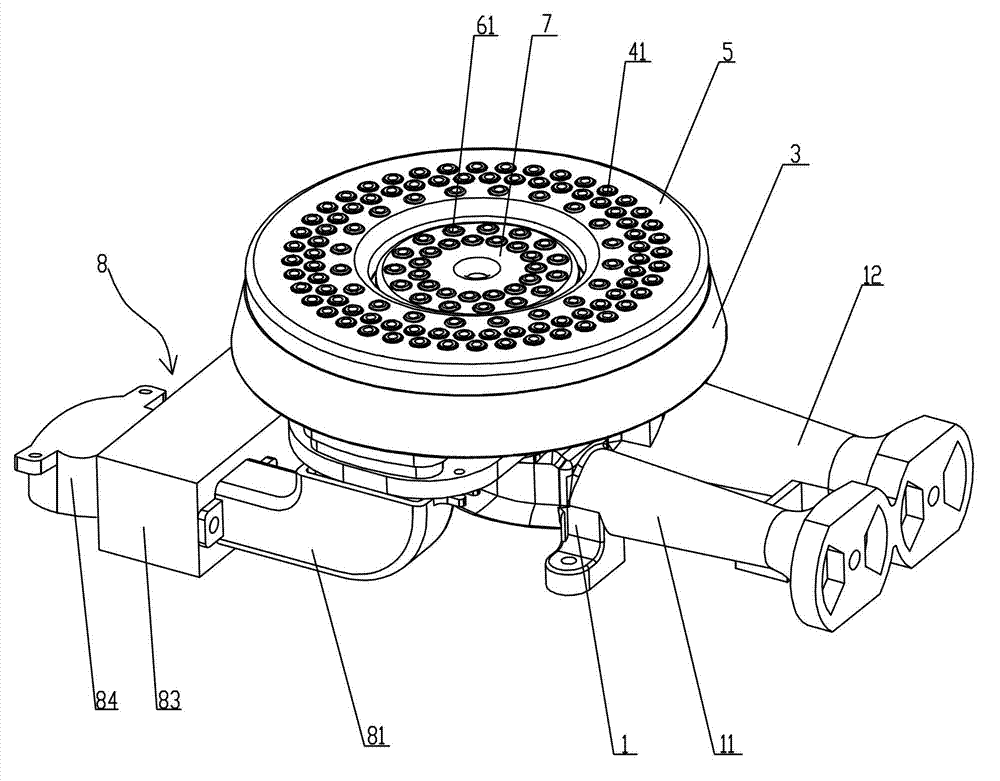
[0020] Example 1, such as Figure 1 to Figure 4 As shown, a blast burner, a blast burner, includes a burner 1, the burner 1 is provided with an inner injection tube 11 and an outer injection tube 12, the primary air is from the burner 1 The shrinking tube of the gas is mixed with the gas and then enters the inner ring injection tube 11 and the outer ring injection tube 12 . Burner head 1 is provided with burner base 2, and burner base 2 is provided with outer ring air passage 21, inner ring air passage 22, and inner ring gas passage 23 communicated with inner injection pipe 11 and with outer injection pipe. The outer ring gas channel 24 communicated with 12; the burner base 2 is equipped with a blast device 8, and the blast device 8 is provided with an outer ring air pipe 81 communicated with the outer ring air channel 21 and an inner ring air tube 81 communicated with the inner ring air channel 22. Ring air pipe 82 , the blower device 8 includes a fan 84 , and an air distrib...

Embodiment 2

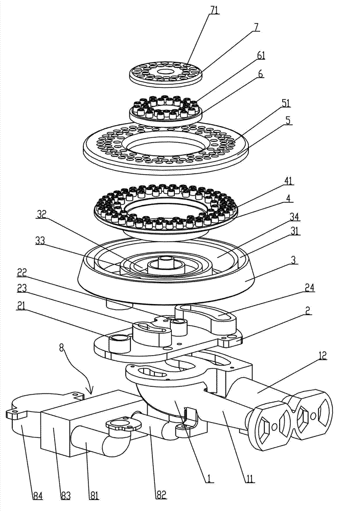
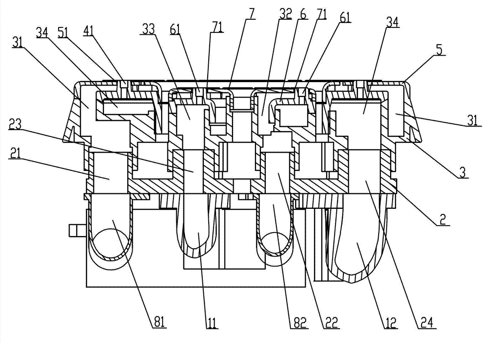
[0021] Example 2, such as Figures 5 to 7 As shown, the difference from Embodiment 1 is that the outer ring gas passage 34 is arranged outside the outer ring air passage 31, the outer fire cover 4 covers the outer ring air passage 31, and the outer ring cover 5 covers the outer ring gas passage 34 , the outer ring air channel 31, the outer ring fire hole 41, the outer ring cover hole 51 and the outer ring gas channel 34 communicate in sequence, the secondary air flows out from the outer ring fire hole 41, and the gas flows out through the outer ring cover hole 51, The fire outlets converge, so that the middle of the fire outlet is secondary air, and the surrounding gas is supplemented. Each fire outlet has a separate hole to supplement air, so that each fire outlet can be supplemented with secondary air independently. The inner ring air channel 32 is arranged on the outer side of the inner ring gas channel 33, the inner fire cover 6 covers the inner ring air channel 32, the in...


PUM


Abstract

The invention relates to a blast type combustor, comprising a furnace end, wherein an inner injection pipe, an outer injection pipe and a furnace end base are arranged on the furnace end. According to the technical main points, a first outer ring air channel, a first inner ring air channel, a first inner ring gas channel and an first outer ring gas channel are arranged on the furnace end base; a blast device is mounted on the furnace end base; an outer ring air pipe and an inner ring air pipe are arranged on the blast device; a distributor is further arranged on the furnace end base; a second outer ring air channel, a second inner ring air channel, a second inner ring gas channel and a second outer ring gas channel are arranged on the fire distributor; an outer fire cover and an inner fire cover are arranged on the fire distributor; an outer ring cover is arranged on the outer fire cover; a plurality of outer ring fire holes are formed in the outer fire cover; an outer ring cover hole is formed in the outer ring cover; an inner ring cover is arranged on the inner fire cover; a plurality of inner ring fire holes are formed in the inner fire cover; and an inner ring cover hole is formed in the inner ring cover. According to the blast type combustor provided by the invention, each fire outlet can individually supply secondary air; an air amount is controllable and air can be uniformly distributed, so that the combustion efficiency is higher.

Description

【Technical field】 [0001] The invention relates to a burner, in particular to a blast type burner. 【Background technique】 [0002] At present, there are all kinds of blast stove burners on the market, but in terms of structure, they are nothing more than primary air blast burners, secondary air blast burners, primary air, and secondary air burners. At the same time blast burner; and the secondary air blast burner on the market, the secondary air is naturally diffused and shunted after reaching the surface of the fire cover through the channel, which is limited to the layout of the fire hole, the structure of the air distribution cavity, and the shape of the fire cover , it is difficult to achieve the uniformity of secondary air distribution, which affects the combustion conditions, especially for burners with multiple rows of fire holes, it is difficult to achieve high energy and high efficiency. 【Content of invention】 [0003] The purpose of the present invention is to ov...

Claims


Application Information

Patent Timeline
Patent Type & Authority Applications(China)
IPC IPC(8): F23D14/04F23D14/46
Inventor 黄启均王莹张喜杰刘海平吴谢军
Owner VATTI CORP LTD
Why Eureka
Try Eureka