Pneumatic tire

A pneumatic tire, tire circumferential technology, applied in tire parts, tire tread/tread pattern, transportation and packaging, etc., can solve the problems of slow recovery, unstable extreme movement, etc., and achieve the effect of improving rigidity

Active Publication Date: 2013-04-10
SUMITOMO RUBBER IND LTD
View PDF7 Cites 25 Cited by
  • Summary
  • Abstract
  • Description
  • Claims
  • Application Information

AI Technical Summary

Problems solved by technology

[0004] However, the above-mentioned pneumatic tires have the following problems: when turning on ice and snow roads, if the limit is exceeded, it is easy to cause a sudden slide, and in addition, the recovery from the slide to the road grip is slow, etc. making extreme movements unstable

Method used


Image

  • Pneumatic tire
  • Pneumatic tire
  • Pneumatic tire

Examples


Embodiment

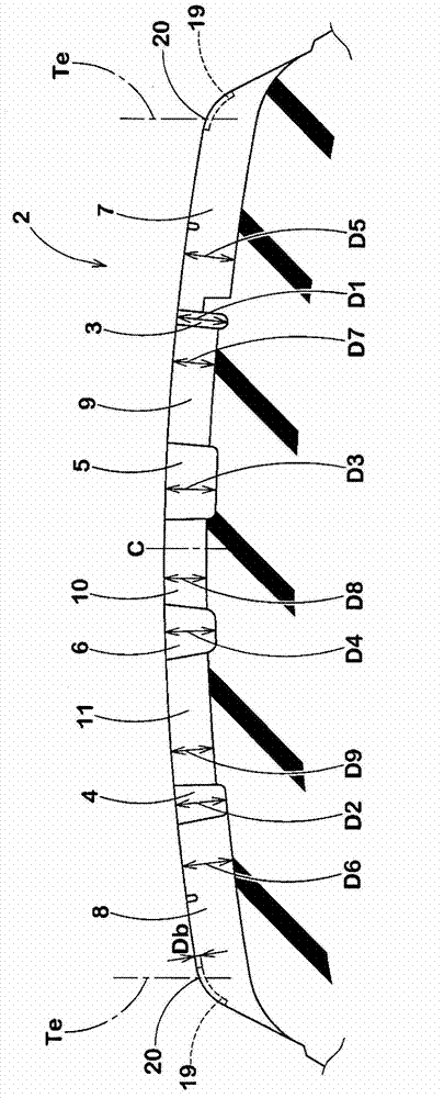
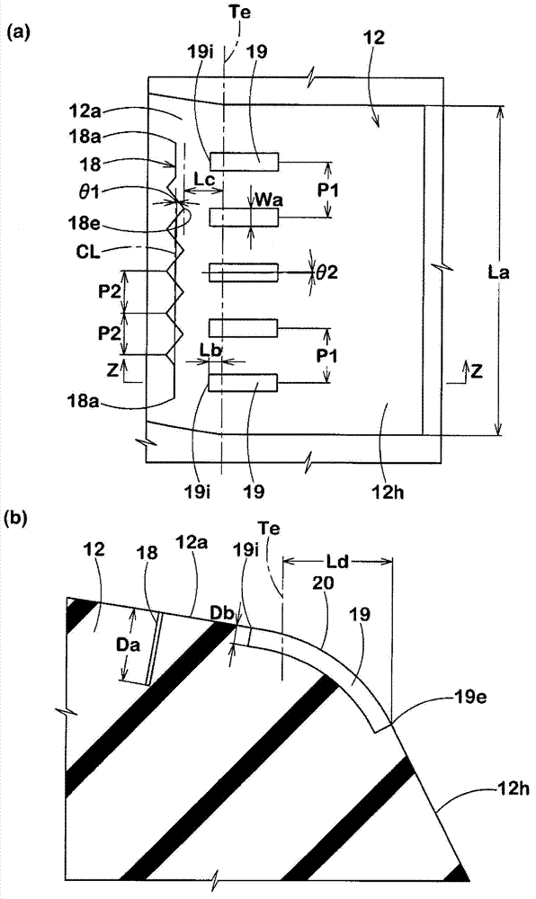
[0056] Based on the specifications in Table 1, a trial production with figure 1 The size of the basic structure of the tread portion shown is a pneumatic tire of 195 / 65R15, and the cornering performance of each trial tire and the extreme action on icy roads and snowy roads were tested. In addition, the shared specifications are as follows.

[0057] Tread contact width TW: 162mm

[0058] Distance L6 / TW between the outer central main groove and the tire equator: 8.0%

[0059] Distance L7 / TW between inner central main groove and tire equator: 9.3%

[0060] Ratio L2 / Le of the block width of the inner shoulder blocks formed at the M pitch to the tire circumferential length: 100%

[0061] The ratio L1 / L2 of the block width of the outer shoulder block to the inner shoulder block: 1.2

[0062] Sipe depth Da of longitudinal sipe: 5.0mm

[0063] The test method is as follows.

[0064]

[0065] Under the conditions of 15×6.0J rim and 200kPa internal pressure, install each test ti...


PUM


Abstract

The present invention provides a pneumatic tire capable of evenly improving cornering performance and behavior in critical cornering on snowy / icy roads. The direction of the pneumatic tire to be arranged to a vehicle is specified. Outboard shoulder block (12) and inboard shoulder blocks (13) are formed at a tread portion (2). Both the outboard / inboard shoulder blocks (12, 13) are provided with sipes. The outboard shoulder blocks (12) have an axial width more than the axial width of the inboard shoulder blocks (13). The circumferential sipe (18) of the outboard shoulder blocks (12) extending at an angle of not more than 10 degrees with respect to the tire circumferential direction is arranged at the side of an outboard tread edge (Te) of the vehicle in sipes (17). The outboard shoulder block (12) has an axially outer sidewall (12h) of which surface is provided with a plurality of narrow buttress grooves (19) extending radially inwardly from the outboard tread edge (Te).

Description

technical field [0001] The present invention relates to a pneumatic tire that balances improvement in cornering performance and extreme movement when cornering on icy and snowy roads. Background technique [0002] Conventionally, there has been a demand for pneumatic tires capable of improving running performance on icy and snowy roads and steering stability on dry roads. Therefore, there is known a tire in which the rigidity of the outer side of the vehicle is greater than that of the inner side of the vehicle in the land portion of the tread portion to improve steering stability, and not only the tread portion is provided with sipes extending in the tire axial direction, A longitudinal sipe extending in the tire circumferential direction is disposed near the end, thereby improving cornering performance on snowy or icy roads. There is the following Patent Document 1 as a related art document. [0003] Patent Document 1: Japanese Patent Application Laid-Open No. 11-321240 ...

Claims


Application Information

Patent Timeline
Patent Type & Authority Applications(China)
IPC IPC(8): B60C11/03B60C11/12
CPCB60C11/01B60C11/0304B60C11/1218B60C11/0306B60C2011/0353B60C2011/0348B60C11/1236Y10S152/03Y10S152/902B60C11/04B60C11/11B60C11/12
Inventor 景山尚纪
Owner SUMITOMO RUBBER IND LTD
Why Eureka
Try Eureka