Eureka AIR delivers breakthrough ideas for toughest innovation challenges, trusted by R&D personnel around the world.

Resource distribution method and resource distribution device

A technology of resource allocation and resource division, applied in electrical components, wireless communication and other directions, which can solve the problems of multi-RB resources and low frequency band utilization.

Active Publication Date: 2013-04-03
ZTE CORP
View PDF4 Cites 9 Cited by
  • Summary
  • Abstract
  • Description
  • Claims
  • Application Information

AI Technical Summary

Problems solved by technology

At the same time, since PUCCH formats 2 / 2a / 2b only have frequency-domain code division multiplexing, the frequency band utilization of PUCCH formats 2 / 2a / 2b is lower than that of PUCCH formats 1 / 1a / 1b. According to the system cell capacity requirements, PUCCH formats 2 / 2a / 2b may occupy more RB resources
In order to improve the utilization of frequency band resources, it is necessary to reduce the number of RBs occupied by the control channel as much as possible, so the number of RBs occupied by PUCCH formats 2 / 2a / 2b Should not be configured too large

Method used


Image

  • Resource distribution method and resource distribution device
  • Resource distribution method and resource distribution device
  • Resource distribution method and resource distribution device

Examples


Embodiment Construction

[0024] In order to make the technical problems, technical solutions and beneficial effects to be solved by the present invention clearer and clearer, the present invention will be further described in detail below in conjunction with the accompanying drawings and embodiments. It should be understood that the specific embodiments described here are only used to explain the present invention, not to limit the present invention.

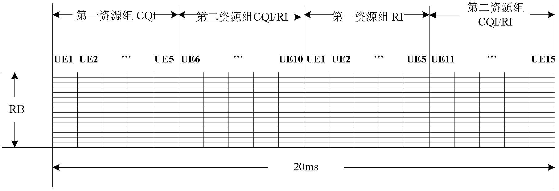
[0025] like figure 1 As shown, the embodiment of the present invention provides a resource allocation method, and its specific processing flow is as follows:

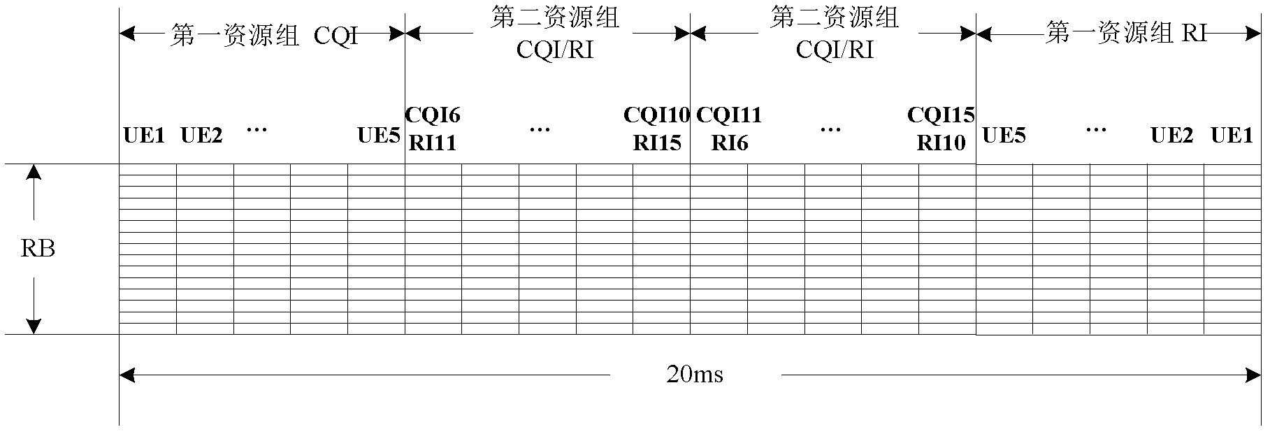
[0026] Step 11: Divide the PUCCH resources to be allocated and format 2 / 2a / 2b (also referred to as PUCCH formats 2 / 2a / 2b resources) into a first resource group and a second resource group, wherein the first resource group uses In order to ensure that the CQI / PMI and RI of the same UE do not overlap, and that the CQI / PMI and RI between different UEs do not overlap, the second resource group is us...


PUM


Abstract

The invention discloses a resource distribution method and a resource distribution device. The method comprises the following steps of: dividing physical uplink chain control channel (PUCCH) resources which are to be distributed and have the formats of 2 / 2a / 2b into a first resource group and a second resource group; determining that the PUCCH resources with the formats of 2 / 2a / 2b are required to be distributed to user equipment (UE); judging whether a transmission mode of the UE is TM3, TM4, TM8 or TM9; and if the transmission mode is TM3, TM4, TM8 or TM9, distributing the PUCCH resources from the first resource group to the UE, otherwise, distributing the PUCCH resources from the second resource group to the UE. By utilizing the technical scheme, when the resources are distributed to the PUCCH with the formats of 2 / 2a / 2b, on the premise of guaranteeing that control information CQI / PMI / RI is effectively submitted, the frequency band resource utilization rate is effectively improved.

Description

technical field [0001] The present invention relates to the technical field of mobile communication, in particular to a resource allocation method and device. Background technique [0002] The Physical Uplink Control Channel (PUCCH, Physical Uplink Control Channel) is a physical channel for transmitting uplink control information in the Long Term Evolution (LTE, Long Term Evolution) system. The function of the PUCCH is to transmit uplink control information that has nothing to do with data, such as Uplink Control Information (UCI, Uplink Control Information). The PUCCH is distributed in a frequency region at the edge of the bandwidth of the LTE system, and it supports multiple formats (formats), wherein the UCI transmitted by the PUCCH formats 2 / 2a / 2b is a channel quality indicator (CQI, Channel Quality Indicator) / precoding matrix indicator ( PMI, Precoding Matrix Indicator) / rank indicator (RI, Rank Indicator), or multiplexing of CQI / PMI / RI and acknowledgment signal (ACK, A...

Claims


Application Information

Patent Timeline
IPC IPC(8): H04W72/04
CPCH04W72/0453
Inventor 李军
Owner ZTE CORP
Why Eureka
Eureka Blog
Learn More