Commutator bearing mechanism for automatic rotor commutator press-in machine

A technology of bearing mechanism and commutator, which is applied in the manufacture of motor generators, electromechanical devices, electric components, etc. It can solve the problems that affect the production capacity and output value, the pressing is not in place, and the motor casing cannot be installed, so as to achieve a simple design structure Practical and prevents misplacement

Inactive Publication Date: 2013-04-03
SUZHOU BODE AUTOMATION TECH
View PDF3 Cites 3 Cited by
  • Summary
  • Abstract
  • Description
  • Claims
  • Application Information

AI Technical Summary

Problems solved by technology

[0002] In modern industrial manufacturing, many complex machines are assembled manually, including mobile phones and computers in the electronics industry, as well as automobile manufacturing and other household appliances; these industrial manufacturing requires a lot of small assembly Links are assembled together. For example, the motor assembly of electric window lifters in automobile production is assembled manually. Due to human factors, there will be deviations and efficiency problems in assembly, which will affect the overall production capacity and output value. The rotor of the motor is More important parts, the rotor of the motor changes the magnetic poles by changing the direction of electricity. There is a commutator near the rotor coil. The commutator is an interference fit on the rotor shaft, which needs to be assembled in place by pressing. Ordinary When manually pressing, it often occurs that it is over-pressed and broken or the pressing is not in place, and it cannot be installed into the motor casing.

Method used


Image

  • Commutator bearing mechanism for automatic rotor commutator press-in machine

Examples


Embodiment Construction

[0007] The preferred embodiments of the present invention will be described in detail below in conjunction with the accompanying drawings, so that the advantages and features of the invention can be more easily understood by those skilled in the art, so as to define the protection scope of the present invention more clearly.

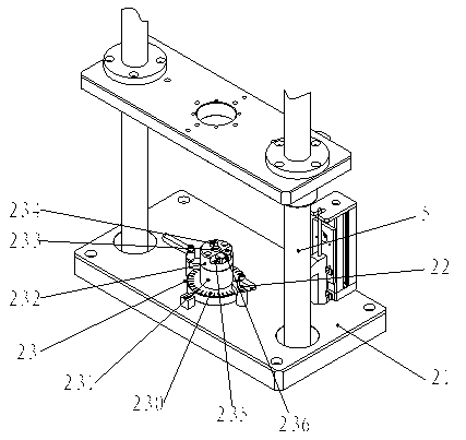
[0008] see figure 1 , the embodiment of the present invention includes:

[0009] A commutator carrying mechanism of a rotor commutator automatic press-in machine, the commutator support mechanism of the rotor commutator automatic press-in machine includes a bottom plate 21 with a commutator jig 23 fixed in the middle through a quick handle 22, the bottom plate The two sides of 21 are provided with guide bar 5; Described commutator jig 23 is that the cylindrical seat 231 upper end of band lower fixed side 230 is provided with commutator inserting disc 232, and commutator inserting disc 232 middle is provided with inserting hole 233 The commutator insert ...


PUM


Abstract

The invention discloses a commutator bearing mechanism for an automatic rotor commutator press-in machine. The commutator bearing mechanism for the automatic rotor commutator press-in machine comprises that a commutator fixture is fixed in the middle of a bottom plate through a rapid handle; guide rods are arranged on two sides of the bottom plate; the commutator fixture is that a commutator insertion disc is arranged at the upper end of a cylindrical seat with a lower fixing side; an insertion hole is formed in the middle of the commutator insertion disc; a positioning column pin is arranged on the commutator insertion disc on the left side of the insertion hole; a lower concave small platform is arranged on the right side of the commutator insertion disc; and two positioning gauge blocks are fixed on the small platform. Due to the mode, the commutator bearing mechanism is simple and practical in design structure, the commutator can be accurately and rapidly arranged in the clamp, and the commutator is effectively prevented from being dislocated.

Description

technical field [0001] The invention relates to the field of automatic assembly machinery, in particular to a commutator bearing mechanism of a rotor commutator automatic press-in machine. Background technique [0002] In modern industrial manufacturing, many complex machines are assembled manually, including mobile phones and computers in the electronics industry, as well as automobile manufacturing and other household appliances; these industrial manufacturing requires a lot of small assembly Links are assembled together. For example, the motor assembly of electric window lifters in automobile production is assembled manually. Due to human factors, there will be deviations and efficiency problems in assembly, which will affect the overall production capacity and output value. The rotor of the motor is More important parts, the rotor of the motor changes the magnetic poles by changing the direction of electricity. There is a commutator near the rotor coil. The commutator is...

Claims


Application Information

Patent Timeline
Patent Type & Authority Applications(China)
IPC IPC(8): H02K15/00
Inventor 邹世旺
Owner SUZHOU BODE AUTOMATION TECH
Why Eureka
Try Eureka