
A microgrid control method and device

A control method and microgrid technology, applied in the direction of AC network load balancing, etc., can solve the problems of increasing investment cost, reducing the reliability of microgrid power supply, and increasing the configuration requirements of main power supply capacity, so as to reduce investment cost and reduce capacity. Configuration requirements, the effect of improving reliability

Active Publication Date: 2016-03-30
ELECTRIC POWER RES INST OF STATE GRID ZHEJIANG ELECTRIC POWER COMAPNY +1
View PDF3 Cites 0 Cited by
  • Summary
  • Abstract
  • Description
  • Claims
  • Application Information

AI Technical Summary

Problems solved by technology

[0004] However, in the above operation mode, when the microgrid has transient power fluctuations, the transient power fluctuations are all borne by the energy storage inverter as the main power supply, thereby reducing the power supply reliability of the microgrid and further increasing the energy consumption of the microgrid. The capacity configuration requirements of the main power supply increase the investment cost

Method used


Image

  • A microgrid control method and device
  • A microgrid control method and device
  • A microgrid control method and device

Examples


Embodiment 1

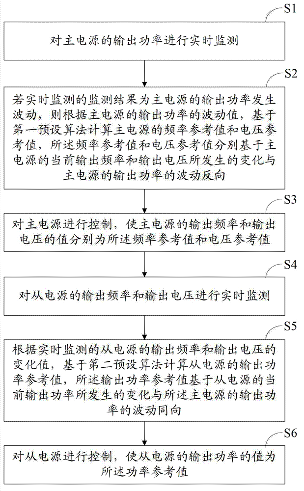
[0053] Embodiment 1 of the present invention discloses a microgrid control method, please refer to figure 2 , the microgrid control method includes the steps of:

[0054] S1: Real-time monitoring of the output power of the main power supply.

[0055] Among them, the output power includes active power and reactive power.

[0056] Taking the above-mentioned microgrid as an example, the output power of the main power supply can be monitored in real time. Specifically, the corresponding acquisition circuit or collector can be used, and the acquisition circuit or collector can be connected to the bidirectional inverter built in the main power supply through a high-speed communication network. It is connected to the main power controller in the device, and the active power and reactive power of the main power are collected from the main power controller in real time; and based on the collection, it is judged whether the active power and reactive power of the main power fluctuate. ...

Embodiment 2

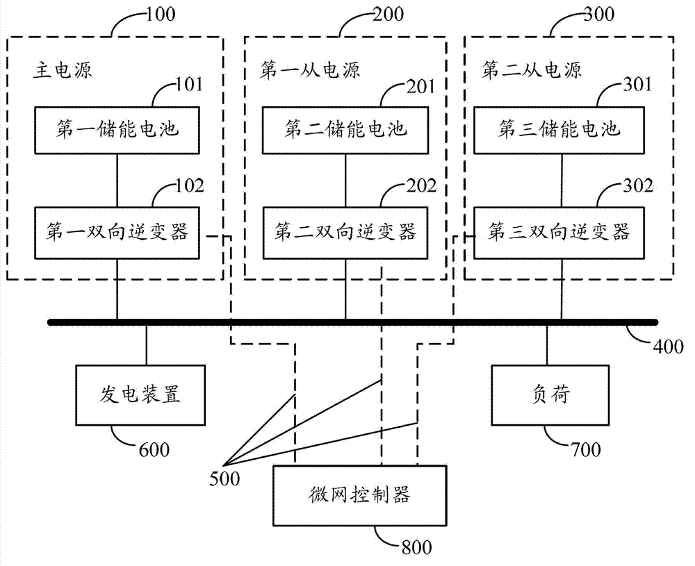
[0110] Embodiment 2 of the present invention discloses a micro-grid control device based on the micro-grid control method provided in Embodiment 1. Please refer to Figure 7 , the microgrid control device includes a main power monitoring module 701, a main power calculation module 702, a main power control module 703, a slave power monitoring module 704, a slave power calculation module 705 and a slave power control module 706, wherein:

[0111] The main power supply monitoring module 701 is configured to monitor the output power of the main power supply in real time.

[0112] The main power calculation module 702 is configured to calculate the frequency reference value and the voltage reference value of the main power based on a first preset algorithm according to the fluctuation value of the output power of the main power when the output power of the main power fluctuates according to the monitoring result of real-time monitoring. The frequency reference value and the voltag...


PUM


Abstract

The invention discloses a micro-grid control method. The micro-grid control method includes: monitoring output power of a master power supply; if the output power of the master power supply fluctuates, computing a frequency reference value and a voltage reference value of the master power supply according to a fluctuating value; controlling the master power supply to enable output frequency and output voltage thereof to be the frequency reference value and the voltage reference value respectively; monitoring the output frequency and the output voltage of the power supply; computing an output power reference value of slave power supplies according to monitored change values of output frequency and output voltage of the slave power supplies; and controlling the slave power supplies to enable output power thereof to be the power reference value. Besides, change of the output power of the slave power supplies and fluctuation of the output power of the master power supply are in the same direction. Clearly, the micro-grid control method has the advantages that by means of finally controlling the output power of the slave power supplies, energy-storing inverters share power fluctuation when a micro-grid is in power fluctuation, so that reliability of the micro-grid is improved, capacity allocation requirements of the master power supply are lowered, and investment cost is reduced.

Description

technical field [0001] The invention belongs to the technical field of micro-grid control, and in particular relates to a micro-grid control method and device. Background technique [0002] Microgrid has huge social and economic benefits, and it is the most effective way to exert the efficiency of distributed power. The operation and control characteristics of the microgrid itself require it to adopt distributed energy storage. As the core link in the microgrid, energy storage plays a vital role in the stable operation of the microgrid, energy optimization management, short-term power supply, and improvement of power quality. . [0003] At present, the energy storage system of the microgrid adopts the mixed use of energy-type energy storage and power-type energy storage. Due to the limited power of a single energy storage inverter, multiple energy storage inverters are usually selected for larger energy storage capacity. Parallel structure, based on the above reasons, it i...

Claims


Application Information

Patent Timeline
Patent Type & Authority Patents(China)
IPC IPC(8): H02J3/32
Inventor 周丹李鹏汪科张雪松赵波葛晓慧周金辉
Owner ELECTRIC POWER RES INST OF STATE GRID ZHEJIANG ELECTRIC POWER COMAPNY
Learn More