Novel conductor connector

A conductor and a new type of technology, applied in the direction of multi-conductor connectors, conductive connections, connections, etc., can solve problems such as high cost, many parts, and poor versatility of parts

Active Publication Date: 2013-04-03
YIHE ELECTRIC GRP
View PDF3 Cites 0 Cited by
  • Summary
  • Abstract
  • Description
  • Claims
  • Application Information

AI Technical Summary

Problems solved by technology

[0002] The conductor connection in the existing gas-insulated metal-enclosed switchgear is generally connected through the shield cover, contact seat, plum blossom contact, and insulator, which involves many parts, the structure is more complicated, and the versatility of the parts is poor. There are more silver-plated surfaces on the contact surface, and the cost is higher

Method used


Image

  • Novel conductor connector
  • Novel conductor connector
  • Novel conductor connector

Examples


Embodiment 1

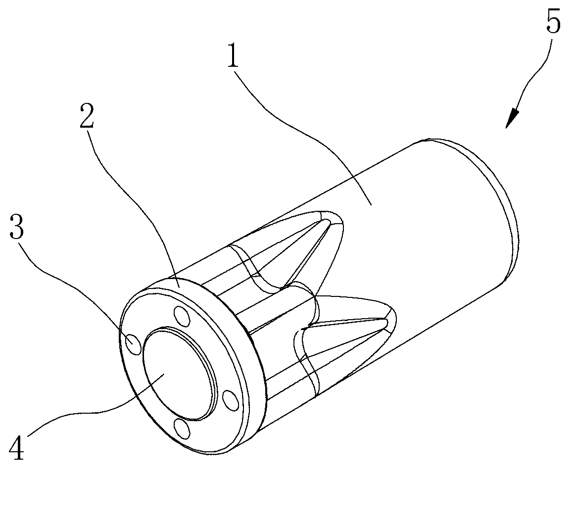
[0019] to combine figure 1 and Figure 4 , a new type of conductor joint, including a straight conductor 1, one end of the straight conductor 1 is a connecting flange 2, there are four mounting holes 3 on the connecting flange 2, and a circular protrusion is provided in the middle of the outer end of the connecting flange 2 Surface 4, a section from the middle of the straight conductor 1 to the connecting flange 2 has a quincunx-shaped section. The other end of the straight conductor 1 is a single-ended connector 5 .

[0020] This type of conductor joint is used for straight-through connection of gas-insulated metal-enclosed switchgear.

Embodiment 2

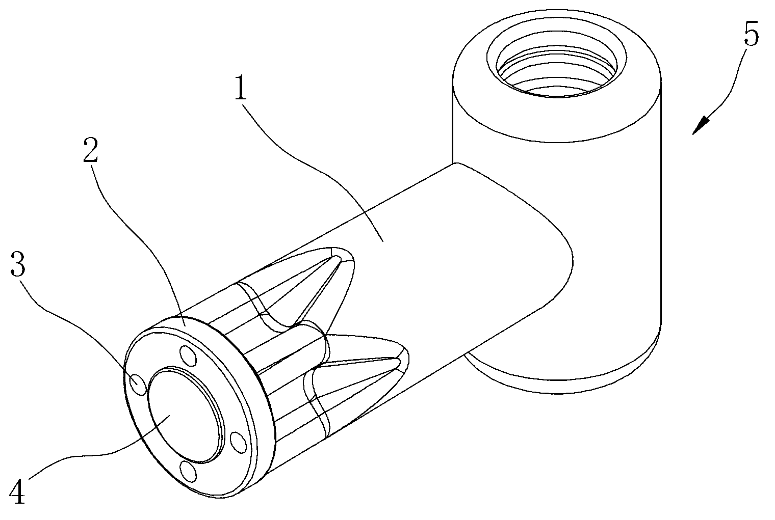
[0022] to combine figure 2 and Figure 4 , a new type of conductor joint, including a straight conductor 1, one end of the straight conductor 1 is a connecting flange 2, there are four mounting holes 3 on the connecting flange 2, and a circular protrusion is provided in the middle of the outer end of the connecting flange 2 Surface 4, a section from the middle of the straight conductor 1 to the connecting flange 2 has a quincunx-shaped section. The other end of the straight conductor 1 is a double-ended joint 5 , and the two joints are arranged in a T-shape with the straight conductor 1 .

[0023] This conductor joint is a three-way connection for gas-insulated metal-enclosed switchgear.

Embodiment 3

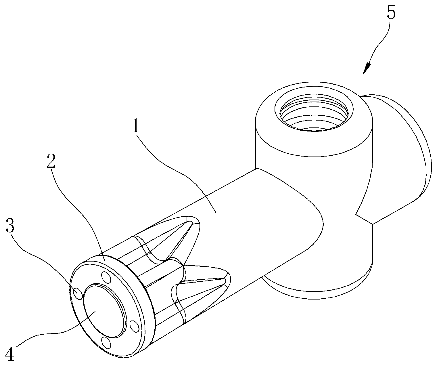
[0025] to combine image 3 and Figure 4 , a new type of conductor joint, including a straight conductor 1, one end of the straight conductor 1 is a connecting flange 2, there are four mounting holes 3 on the connecting flange 2, and a circular protrusion is provided in the middle of the outer end of the connecting flange 2 Surface 4, a section from the middle of the straight conductor 1 to the connecting flange 2 has a quincunx-shaped section. The other end of the straight conductor 1 is a three-head joint 5, and the three joints and the straight conductor 1 are arranged in a cross shape.

[0026] This type of conductor joint is used for four-way connection of gas-insulated metal-enclosed switchgear.

[0027] The new body joint introduced in the above embodiments is directly connected to the insulator by bolts through the connecting flange, and the quincunx structure has the function of shielding, which reduces the use of shielding covers. There is only one contact surface...


PUM


Abstract

The invention discloses a novel conductor connector which comprises a straight conductor. One end of the straight conductor is provided with a connecting flange, four installing holes are arranged on the connecting flange, a circular protrusion face is arranged in the middle of the outer end of the connecting flange, the section of a section from the middle of the straight conductor to the connecting flange is quincunx-shaped, and a single-end connector, a double-end connector or a three-end connector are arranged at the other end of the straight conductor. The novel conductor connector is connected with an insulation piece through a bolt directly through the connecting flange, a quincunx-shaped structure has a shielding effect, and shielding covers are reduced. Only one contact face is arranged in connection, and return circuit resistance is reduced. In addition, the conductor connector is simple in structure, easy to machine and manufacture and low in manufacture cost.

Description

technical field [0001] The invention relates to a connection device in a gas-insulated metal-enclosed switchgear, in particular to a joint for conductor connection. Background technique [0002] The conductor connection in the existing gas-insulated metal-enclosed switchgear is generally connected through the shield cover, contact seat, plum blossom contact, and insulator, which involves many parts, the structure is more complicated, and the versatility of the parts is poor. There are more silver-plated surfaces on the contact surface, and the cost is higher. Therefore, the inventor envisions designing a conductor joint with a simple structure and easy processing and manufacture. Contents of the invention [0003] The purpose of the present invention is to provide a new type of conductor joint, which has a novel structure and is easy to process and manufacture. [0004] In order to achieve the above object, the present invention adopts the technical solution as follows: ...

Claims


Application Information

Patent Timeline
Patent Type & Authority Applications(China)
IPC IPC(8): H01R11/00H01R11/01H01R11/03H02B13/035
Inventor 孔祥冲彭凤娟张世晓荐云勇管竹青张振国冯旭枫
Owner YIHE ELECTRIC GRP
Why Eureka
Try Eureka