
Electrical heating method and circuit of electronic device at low temperature

A technology for electronic equipment and electric heating, which is applied in the direction of using electric means for temperature control, auxiliary controllers with auxiliary heating devices, etc., which can solve the problems of equipment burning, failure to achieve normal working performance, and affecting the opening of electronic equipment circuits. To achieve the effect of efficient work

Inactive Publication Date: 2013-04-03
NANJING PANDA HANDA TECH +3
View PDF4 Cites 6 Cited by
  • Summary
  • Abstract
  • Description
  • Claims
  • Application Information

AI Technical Summary

Problems solved by technology

In this environment, products usually designed for civilian use may not be able to be opened or used, or the performance of the equipment may not meet the standard
The ambient temperature has a great influence on the electronic circuit of the equipment. Low temperature will affect the opening and normal operation of the electronic equipment circuit, and high temperature will affect the electronic equipment circuit opening, overloading, and even equipment burning.
Electronic (electrical) equipment cannot be started, cannot work normally, and cannot achieve normal working performance in a low temperature environment

Method used


Image

  • Electrical heating method and circuit of electronic device at low temperature
  • Electrical heating method and circuit of electronic device at low temperature
  • Electrical heating method and circuit of electronic device at low temperature

Examples


Embodiment Construction

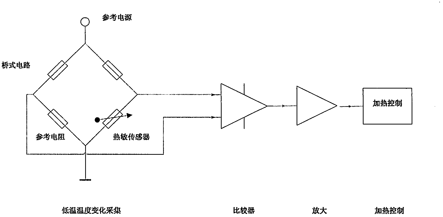
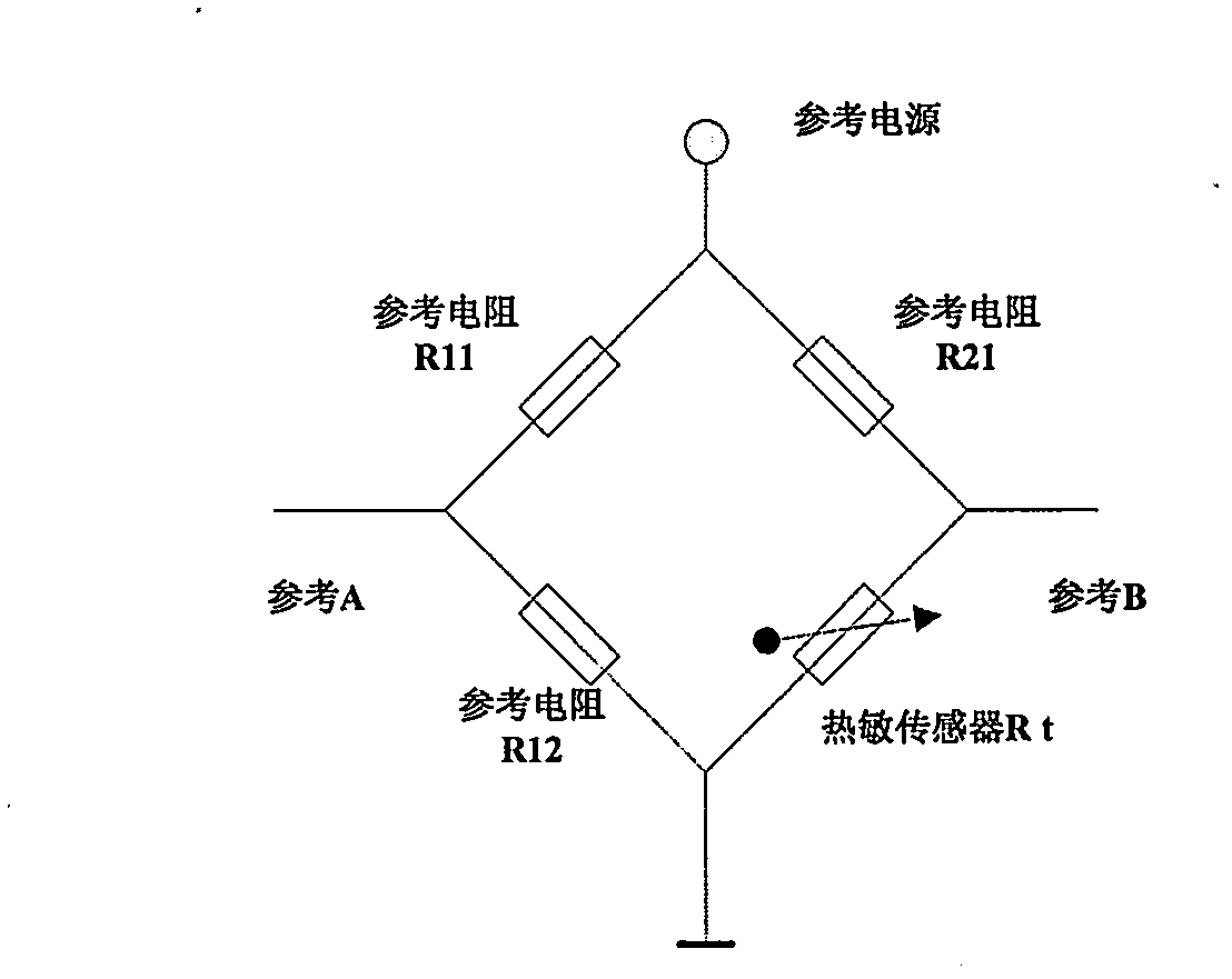
[0018] Acquisition circuit for low-temperature temperature changes of electronic (electrical) equipment: The acquisition circuit for low-temperature temperature changes adopts a bridge circuit, and the four resistors of the four bridge arms are R11, R12, R21, and Rt, where Rt is a thermal sensor -- -Thermistor. Then according to the law of the bridge circuit, there is VA=(R11:R11+R12)V reference power supply, VB=(R21:R21+RT)V reference power supply. When R11:R12=R21:RT, VA=VB, that is, VA-AB=0, is the balance point of the bridge; when a bridge arm changes, R11:R12≠R21:RT, such as the change of the sensitive resistance of RT , VA-AB changes accordingly. Realize the change of temperature into the change of voltage difference.

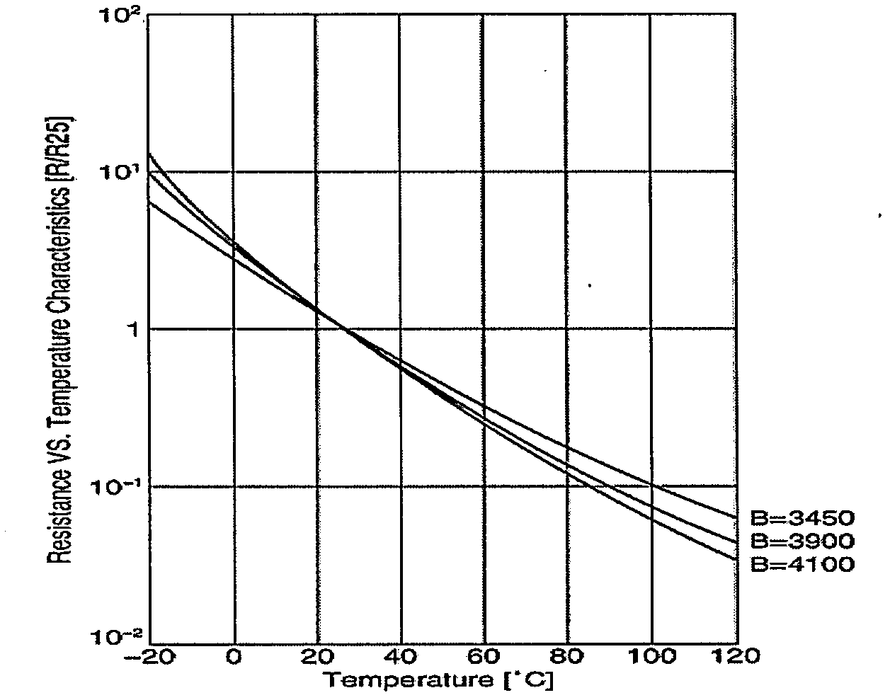
[0019] RT thermistor, for example, select a 10K OHM NTC resistor with a temperature characteristic of 4100, and a resistor with a temperature characteristic of 4100 --- the temperature curve is image 3 , when the temperature drops, the resistance basi...


PUM


Abstract

The invention discloses an electrical heating method of an electronic device at a low temperature, which is used for carrying out low-temperature heating and temperature rise control on the electronic device, and implemented by using a low-temperature area acquisition circuit, a reference comparison circuit, an amplifying circuit and a heating control circuit; a low temperature change acquisition circuit is a bridge circuit, each bridge arm is provided with a resistor, and the resistor of one bridge arm is a thermistor; the temperature changes are transferred into bridge voltage difference value changes; a comparator circuit carries out comparison on voltage difference values VA and VB output by the bridge circuit, and outputs the comparison result to a voltage comparator; the comparator circuit is provided with a hysteresis current control circuit for carrying out hysteresis current control on an unsteady state implemented by that output values jump back and forth near a temperature starting control point value, and when the resistance value is changed to a starting control point value R1 and slightly larger than the R1, a situation that the output jumps occurs; when the resistance value is changed and less than the starting control point value R1, the output is still unchanged; and once the resistance value continues to be reduced to a certain value R2 and the R2 is less than the R1, a situation that the output jumps occurs.

Description

1. Technical field [0001] The invention relates to an electric heating method and circuit, especially a design technology for expanding the low-temperature working area of ​​electronic circuits for electronic (electrical) equipment under low-temperature conditions. The control design is versatile and practical. 2. Background technology [0002] Currently, each electronic device has two temperature ranges, namely ambient / operating (ambient / operating) temperature range and storage (storage) temperature range. According to the manufacturing process, electronic devices are divided into three types, namely commercial grade, industrial grade, and military grade. The allowable operating temperature range is generally 0-70°C for commercial grades, -40-85°C for industrial grades, and -55-125°C for military grades. Usually, the actual ambient temperature in most parts of my country in winter will be below 0°C, and in the northeast at high latitudes will be below -20°C, and the extre...

Claims


Application Information

Patent Timeline
IPC IPC(8): G05D23/30
Inventor 严纬华赵安
Owner NANJING PANDA HANDA TECH
Learn More