Eureka AIR delivers breakthrough ideas for toughest innovation challenges, trusted by R&D personnel around the world.

Drying roller and asphalt agitating device

A technology for drying drums and cylinders, which is applied in the field of asphalt mixing equipment, and can solve problems such as environmental pollution, material leakage, and production precision limitations

Active Publication Date: 2013-04-03
ZOOMLION HEAVY IND CO LTD
View PDF10 Cites 8 Cited by
  • Summary
  • Abstract
  • Description
  • Claims
  • Application Information

AI Technical Summary

Problems solved by technology

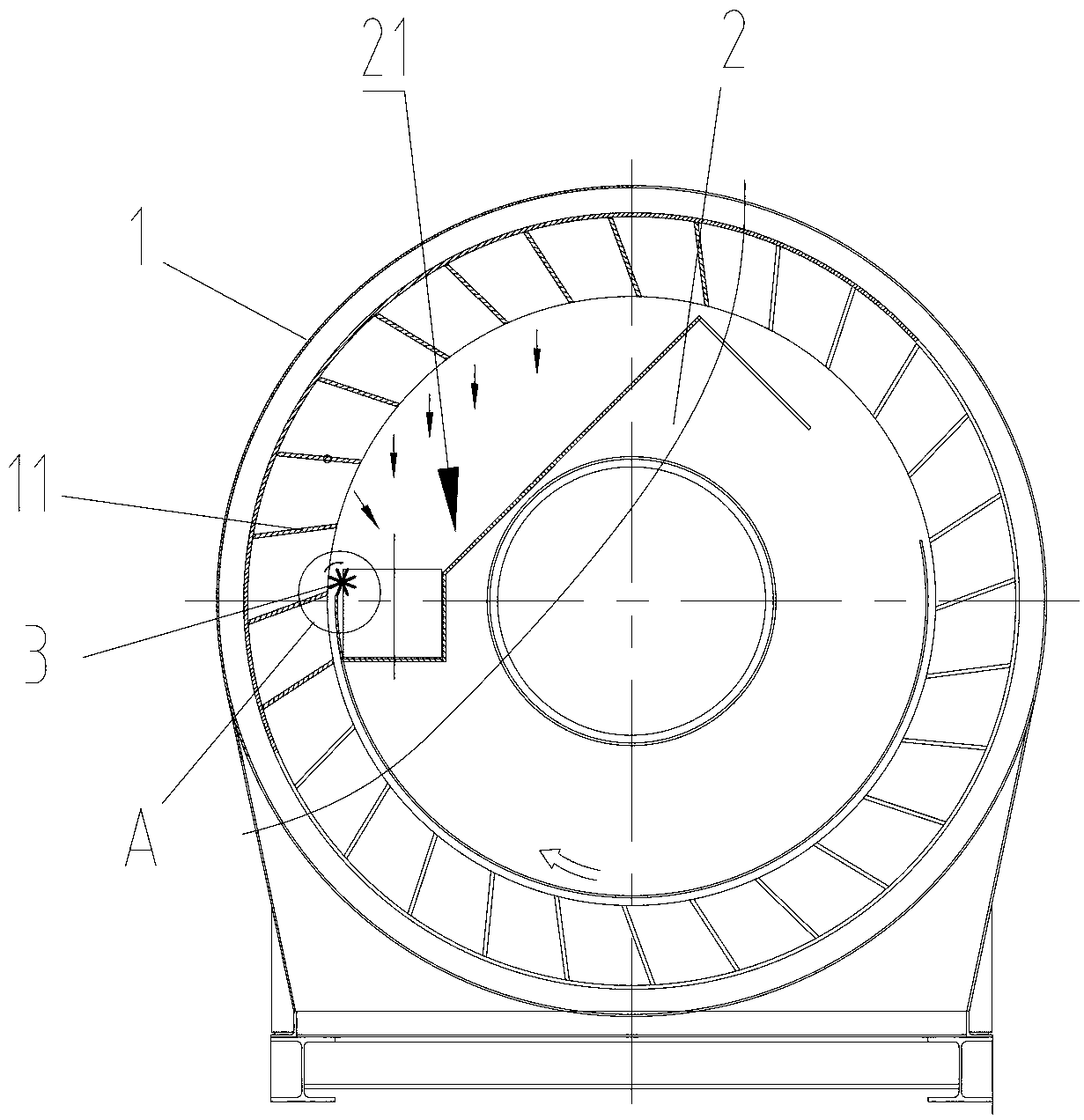
[0003] However, during the discharge process, material leakage often occurs at the discharge end of the cylinder, resulting in low material lifting efficiency of the lifting blades and serious environmental pollution.
The reason for this problem is that neither the cylinder body nor the material receiving box can be machined. It is just a conventional structural part, and its manufacturing accuracy is limited. Leave a relatively large gap between them. Once the gap is not well controlled, stones will run out of the gap, which will affect the lifting efficiency of the drum in the slightest, and leak from the end wall of the drum in severe cases, causing environmental pollution and increasing labor costs.

Method used


Image

  • Drying roller and asphalt agitating device
  • Drying roller and asphalt agitating device
  • Drying roller and asphalt agitating device

Examples


Embodiment Construction

[0032] The specific embodiments of the present invention will be described in detail below with reference to the accompanying drawings. It should be understood that the specific embodiments described herein are only used to illustrate and explain the present invention, and not to limit the present invention.

[0033] In the present invention, if there is no explanation to the contrary, the orientation words used such as "up and down" are usually defined under the normal use of the drying drum provided by the present invention. Specifically, refer to Figure 1 to Figure 7 The directions of the drawings shown, these orientation words are only used to illustrate the present invention, and not to limit the present invention.

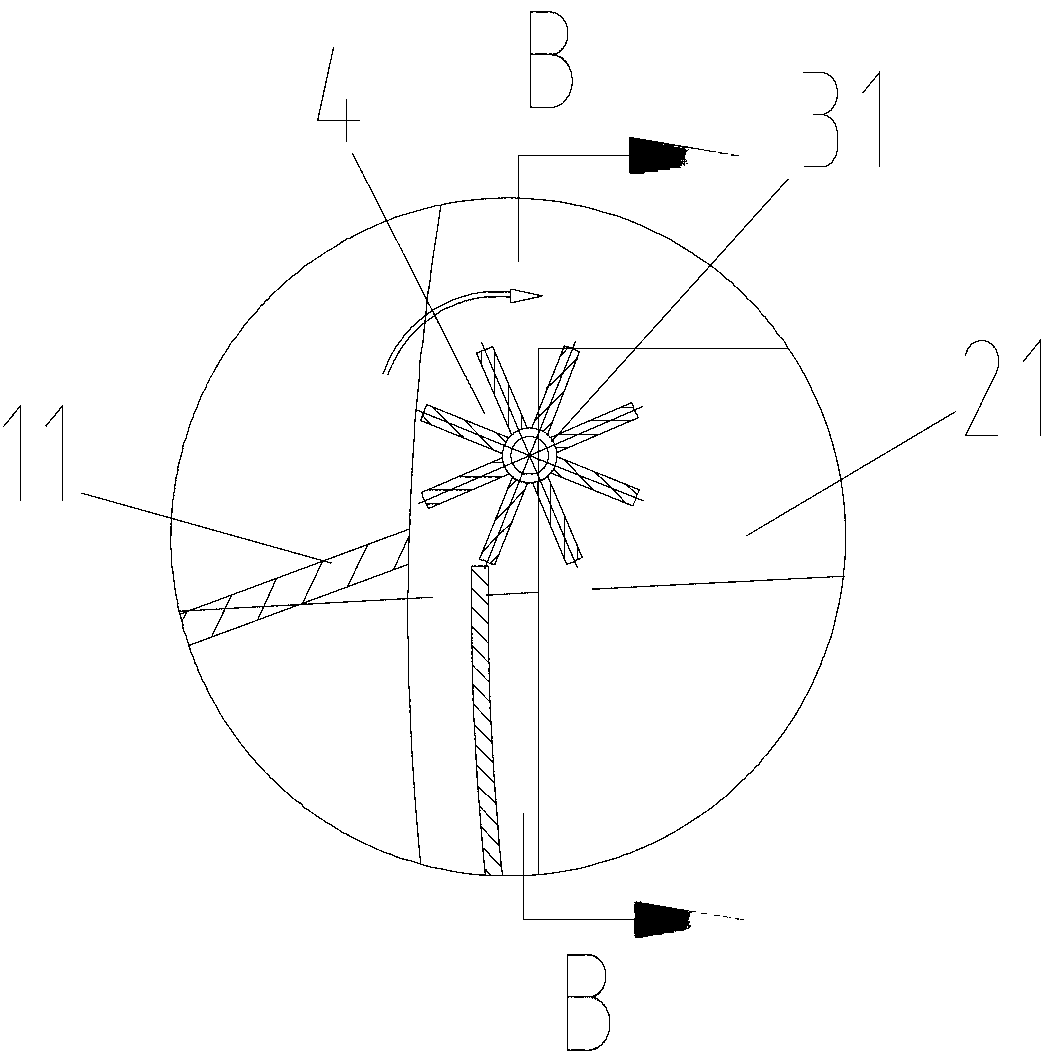
[0034] Below as Figure 1 to Figure 7 As shown, the drying drum provided by the present invention will be described in conjunction with the drying drum used in the asphalt mixing equipment provided by the present invention. It should be understood that the dryin...


PUM


Abstract

The invention discloses a drying roller, which comprises a rotatable barrel (1) and a discharge box (2) at the discharge end of the rotatable barrel (1). A plurality of lifting blades (11) for lifting materials are arranged on the inner wall of the barrel when the barrel rotates. A receiving port (21) of the discharge box corresponds to the lifting blades to receive materials falling from the lifting blades. A receiving mechanism (3) is arranged between the receiving port and the lifting blades. The receiving mechanism conveys materials received to the receiving port. The invention further discloses an asphalt agitating device for the drying roller. As the receiving mechanism which conveys materials to the receiving port is arranged between the receiving port and the lifting blades, material leakage between the feed inlet at the discharge end of the drying roller and the barrel is avoided, so that the lifting efficiency of the lifting blades is improved, and the environmental pollution is avoided.

Description

Technical field [0001] The invention relates to the field of asphalt mixing equipment, in particular to a drying drum and an asphalt mixing equipment using the drying drum. Background technique [0002] Asphalt mixing equipment is the key equipment for pavement construction, used to produce various asphalt mixtures required for pavement construction. The drying drum is also a key component of the asphalt mixing equipment, which can heat and dry materials such as various specifications of sand and gravel to the requirements of the construction specifications. At present, in the prior art, the working principle of the drying drum is that a plurality of lifting blades are arranged in the cylinder, and a material holding tank can be formed between adjacent lifting blades. Therefore, through the rotation of the cylinder, the lifting blades pass through the holding tank. It can lift materials such as sand and gravel to a certain height, and then fall down. In addition, due to the incl...

Claims


Application Information

Patent Timeline
IPC IPC(8): E01C19/08
Inventor 尹友中
Owner ZOOMLION HEAVY IND CO LTD
Why Eureka
Eureka Blog
Learn More