
Drafting device, spinning unit and spinning machinery

A drafting device and drafting technology, applied to spinning machines, free-end spinning machines, continuous winding spinning machines, etc., can solve the problems of difficult connection and blocking, and achieve the effect of reliable suction and leakage prevention

Active Publication Date: 2016-08-10
MURATA MASCH LTD
View PDF7 Cites 0 Cited by
  • Summary
  • Abstract
  • Description
  • Claims
  • Application Information

AI Technical Summary

Problems solved by technology

Therefore, the suction delivery tube itself constitutes a movable part, and it is difficult to perform reliable communication and disconnection.

Method used


Image

  • Drafting device, spinning unit and spinning machinery
  • Drafting device, spinning unit and spinning machinery
  • Drafting device, spinning unit and spinning machinery

Examples


Embodiment Construction

[0039] Next, embodiments of the invention will be described with reference to the drawings.

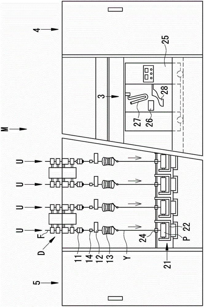
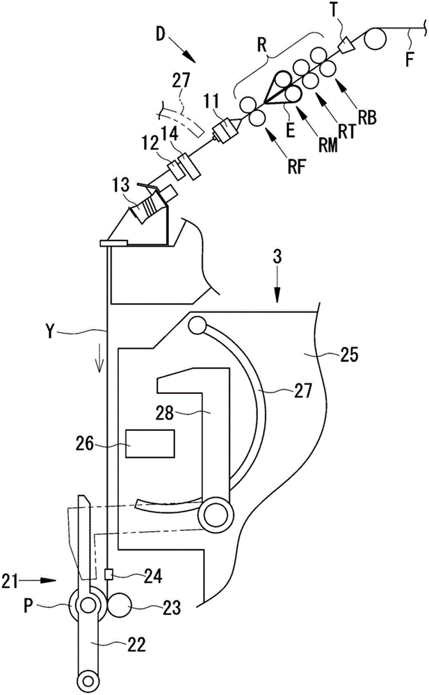
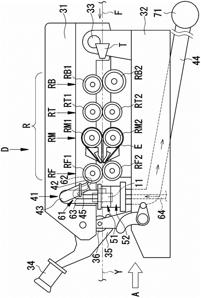
[0040] use Figure 1 to Figure 6 B describes the drafting device D of the first embodiment of the present invention, the spinning unit U and the spinning machine M equipped with the drafting device D.

[0041] First, the outline of the spinning machine M will be described. In addition, in this specification, "upstream" and "downstream" mean upstream and downstream in the movement direction of the fiber bundle F and the spun yarn Y in the spinning unit U.

[0042] Such as figure 1 and figure 2 As shown, the spinning machine M includes a plurality of spinning units U, a splicing trolley 3, a blower box 4, and a power box 5 arranged in parallel. Each spinning unit U includes a draft device D, a spinning device 11, a yarn clearer 12, a yarn slack eliminating device 13, and a winding device 21.

[0043] Such as figure 2 As shown, the drafting device D drafts the fiber bundle (sliver) F supplied...


PUM


Abstract

A draft device includes a roller pair (R), a switching section (31), and a suction section (41). The suction section (41) includes a suction opening (42) adapted to suck fiber dusts in proximity of a top roller, a first suction transporting pipe (43) adapted to transport the fiber dusts sucked through the suction opening (42), and a second suction transporting pipe (44) provided independently from the first suction transporting pipe (43) and adapted to be under a connected state by making contact with the first suction transporting pipe (43) at a drafting position, and an unconnected state by being separated from the first suction transporting pipe (43) at a non-drafting position. The first suction transporting pipe (43) and the second suction transporting pipe (44) are connected at downstream of the most-downstream roller pair (R) in a drafting direction of the fiber bundle (F).

Description

Technical field [0001] The present invention relates to the technology of a drafting device, a spinning unit equipped with a drafting device, and a spinning machine. Background technique [0002] Conventionally, spinning units and spinning machines have been known which draft a fiber bundle by a drafting device and twist the drafted fiber bundle to produce a spun yarn. [0003] The draft device includes a plurality of roller pairs such as a rear roller pair, an intermediate roller pair, and a front roller pair from the upstream side toward the downstream side in the fiber bundle draft direction. Each roller pair is composed of a lower roller as a driving roller and an upper roller that is in contact with the lower roller to follow the rotation. Each upper roller is integrally held on the drafting cradle (hereinafter referred to as the cradle). The cradle rotates freely around a rotating shaft provided at one end. The cradle rotates with the rotating shaft as the center, so that ...

Claims


Application Information

Patent Timeline
Patent Type & Authority Patents(China)
IPC IPC(8): D01H5/66D01H5/22D01H4/02D01H13/00
CPCD01H5/66
Inventor 坂元直孝
Owner MURATA MASCH LTD
Learn More