
Bottle turning mechanism of filling machine

A filling machine and bottle filling technology, which is applied to conveyor objects, transportation and packaging, etc., can solve problems such as affecting filling efficiency, increasing production costs, and inconvenient use. The effect of normal filling and convenient access to the bottle mouth

Inactive Publication Date: 2013-04-03
常州市金坛晨光轻工机械有限公司
View PDF0 Cites 5 Cited by
  • Summary
  • Abstract
  • Description
  • Claims
  • Application Information

AI Technical Summary

Problems solved by technology

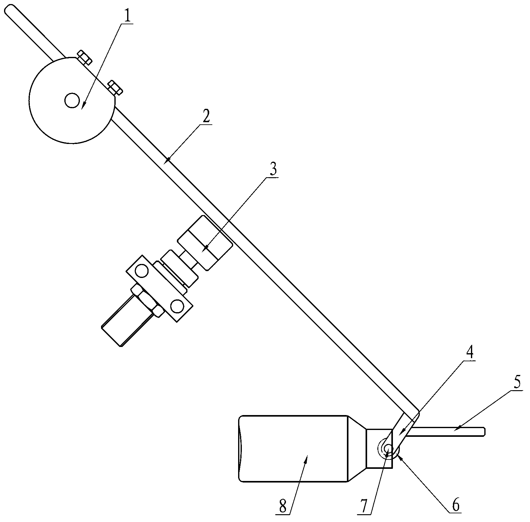
[0003] The bottle turning mechanism of this filling machine has the following deficiencies in the actual use process: when the bottleneck of the bottle body 8 to be filled is relatively large, the bottleneck rod 4 will be stuck in the bottleneck of the bottle body 8 to be filled, resulting in Unsmooth bottle removal, once the bottle is stuck, the bottle body cannot be turned over, the entire filling line will be forced to stop, and the operator will take out the bottle body manually, which will directly affect the filling efficiency. Therefore, the filling enterprise must prepare There are bottle levers 2 of bottle mouth levers 4 of different specifications, although the above-mentioned deficiencies can be overcome like this
However, it is very inconvenient to use. When the specification of the bottle body 8 to be filled is changed, the corresponding bottle lever 2 must be replaced. Not only must the bottle lever 2 of many specifications be prepared, the type and quantity of accessories will be increased, but also the filling efficiency will be affected and the increase will be increased. Cost of production

Method used


Image

  • Bottle turning mechanism of filling machine
  • Bottle turning mechanism of filling machine

Examples


Embodiment 1

[0016] Embodiment 1: a kind of bottle turning mechanism of filling machine, as figure 2 As shown, it includes an adjustable pressure rotary cylinder 1, a bottle lever 2 and a buffer 3. The upper section of the bottle lever 2 is fixedly connected with the rotating shaft of the adjustable pressure rotary cylinder 1, and the buffer 3 is installed in the middle of the bottle lever 2. , the bottom end of the bottle opening bar 2 is provided with a bottle mouth bar 4, the installation angle requirement of the bottle mouth bar 4 and the bottle opening bar 2 is 100°, the length of the bottle mouth bar 4 is 6cm, and the bottle mouth bar 4 is provided with There is an anti-jam rod 5, which is horizontally fixed on the bottle mouth rod 4, the length of the anti-jam rod 5 is 80 mm, and the distance from the lower end of the bottle mouth rod 4 to the confluence of the anti-jam rod 5 and the bottle mouth rod 4 It is 1 / 2~1 of the bottleneck diameter of the bottle body 8 to be filled, and th...


PUM


Abstract

A bottle turning mechanism of a filling machine comprises a pressure-adjustable rotating cylinder, a bottle stirring rod and a buffer, wherein a bottle mouth rod is arranged at the bottom end of the bottle stirring rod; an anti-sticking rod is arranged on the bottle mouth rod and is horizontally fixed on the bottle mouth rod; the length of the anti-sticking rod is larger than the diameter of the bottle mouth of a bottle body to be filled; and the distance from the lower end of the bottle mouth rod to the junction of the anti-sticking rod and the bottle mouth rod is 1 / 2 to 1 of the diameter of the bottle mouth of the bottle body to be filled. When the conveying direction of the bottle mouth of the bottle body to be filled is outward, the bottle mouth rod at the lower end of the bottle stirring rod is positively inserted in the bottle mouth of the bottle body, so that the bottle body is forced to turn for 180 degrees, and then the inverted bottle body can be turned to be placed correctly; through the arrangement of the anti-sticking rod, the bottle mouth rod can be effectively prevented from being stuck in the bottle mouth of the bottle body to be filled; a rolling wheel is arranged at the lower end of the bottle mouth rod, so that the lower end of the bottle mouth rod can enter or go out of the bottle mouth more conveniently; and the bottle turning mechanism improves the adaptability to different bottle bodies, eliminates the phenomenon of bottle sticking and ensures that bottle bodies to be filled are regularly arranged and conveyed in a single direction.

Description

Technical field: [0001] The invention relates to a filling production equipment, in particular to a bottle turning mechanism of a filling machine. Background technique: [0002] In the filling industry, it is a necessary condition that the mouth of the bottle to be filled is output in one direction. The bottle unscrambler on the filling machine can only arrange the bottle to be filled in order to ensure that the bottle to be filled is neatly transported to the bottle conveying belt, but it cannot guarantee that the mouth of the bottle to be filled is output in the same direction. In order to solve this problem, someone invented a bottle turning mechanism, such as figure 1 As shown, it includes an adjustable pressure rotary cylinder 1, a bottle lever 2 and a buffer 3. The upper section of the bottle lever 2 is fixedly connected with the rotating shaft of the adjustable pressure rotary cylinder 1, and the buffer 3 is installed in the middle of the bottle lever 2. , the bottom...

Claims


Application Information

Patent Timeline
Patent Type & Authority Applications(China)
IPC IPC(8): B65G47/248
Inventor 眭小平李卫庆眭文卿郭林山
Owner 常州市金坛晨光轻工机械有限公司
Learn More