Method for forging step shaft with electroslag ingots

A technology of electroslag ingots and stepped shafts, applied in the field of forging, can solve the problems of low utilization rate of forgings, increase of production cost, waste of materials, etc., and achieve the effect of improving utilization rate and enterprise production cost, and saving materials

Inactive Publication Date: 2013-04-03
无锡东鑫铭锻压有限公司
View PDF7 Cites 11 Cited by
  • Summary
  • Abstract
  • Description
  • Claims
  • Application Information

AI Technical Summary

Problems solved by technology

[0002] In the forging method of the existing electroslag ingot stepped shaft, such as figure 1 As shown, the electroslag ingot is cooled by the molten pool to form a riser end 101 after the ingot casting is completed. The riser end 101 is a concave surface formed by the cooling and shrinkage of the solution, and then forged. As the forging ratio increases, the concave surface deepens. Eventually shrinkage holes are formed, such as figure 2 As shown, in order to avoid shrinkage holes, first use the manipulator to press the electroslag ingot with the riser end out of the clamp 102, in order to ensure the forging ratio, as image 3 As shown, then place the pliers 102 in the center of the upsetting drain plate 2, upsetting the electroslag ingot through a hydraulic press to ensure the forging ratio, and finally pull it out through the manipulator, because the concave surface of the riser end has been forged into a pliers , After the final step shaft is completed, both the clamp handle and the riser end are cut off, but this method wastes material, the utilization rate of forgings is low, and the production cost is greatly increased

Method used


Image

  • Method for forging step shaft with electroslag ingots
  • Method for forging step shaft with electroslag ingots
  • Method for forging step shaft with electroslag ingots

Examples


Embodiment Construction

[0018] The specific implementation manner of the present invention will be described below in conjunction with the accompanying drawings.

[0019] The inventive method comprises the following steps:

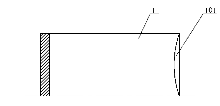
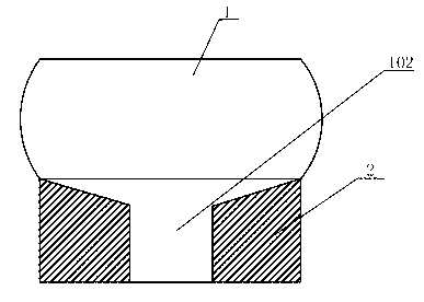
[0020] The first step: if Figure 4 As shown, the electroslag ingot 1 with the riser end 101 is placed on the upset drain plate 2 .

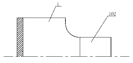
[0021] Step 2: Use a hydraulic machine to upset the electroslag ingot 1. Since the upsetting drain plate 2 is provided with an inner concave surface, after the electroslag ingot 1 is upset by the hydraulic machine, the riser end 101 of the electroslag ingot 1 is upset After that, a drum-shaped convex surface is formed, and the drum-shaped convex surface is as Figure 5 shown.

[0022] Step 3: Use the jaws of the manipulator to hold the electroslag ingot described in step 2, and elongate the electroslag ingot. Since the riser end of the electroslag ingot is a drum-shaped end face, it will not be stretched during the elongation process. produce s...


PUM


Abstract

The invention relates to a method for forging a step shaft with electroslag ingots. The method is suitable for forging the step shaft with large step diameter. A dead head end of an electroslag ingot is disposed on a upsetting drain cap for upsetting. The upset dead head end of the electroslag ingot forms a drum-shaped convex face and is elongated, due to the fact that the dead head end is the drum-shaped convex face, the dead head end is less prone to sinking, only a small part of dead head end needs to be cut off at last, pliers handle pressing with a hydraulic press in the original method is omitted, and the method has the advantages that the method is material-saving, utilization rate of forged piece is improved, and production cost is lowered.

Description

technical field [0001] The invention relates to a forging method, in particular to a forging method for an electroslag ingot forging a stepped shaft which is suitable for a stepped shaft with a large step diameter. Background technique [0002] In the forging method of the existing electroslag ingot stepped shaft, such as figure 1 As shown, the electroslag ingot is cooled by the molten pool to form a riser end 101 after the ingot casting is completed. The riser end 101 is a concave surface formed by the cooling and shrinkage of the solution, and then forged. As the forging ratio increases, the concave surface deepens. Eventually shrinkage holes are formed, such as figure 2 As shown, in order to avoid shrinkage holes, first use the manipulator to press the electroslag ingot with the riser end out of the clamp 102, in order to ensure the forging ratio, as image 3 As shown, then place the pliers 102 in the center of the upsetting drain plate 2, upsetting the electroslag in...

Claims


Application Information

Patent Timeline
IPC IPC(8): B21K1/06B21J5/00B21J5/08
Inventor 谢培德周永达汪建明王东来
Owner 无锡东鑫铭锻压有限公司
Why Eureka
Try Eureka