
Electric screw press control system and electric screw press control method

A technology of electric screw and control system, which is applied to the driving device of presses, manufacturing tools, forging presses, etc. It can solve the problems of prolonged recovery time of sliders, shortened service life of molds, and connection failures, so as to eliminate downtime and prolong The effect of improving the service life and improving the overall reliability of use

Inactive Publication Date: 2013-04-03
青岛宏达锻压机械有限公司
View PDF0 Cites 10 Cited by
  • Summary
  • Abstract
  • Description
  • Claims
  • Application Information

AI Technical Summary

Problems solved by technology

[0011] The purpose of the present invention is to provide a control system and control method for an electric screw press, aiming to solve the problem that the shaft end position sensor of the main motor of the electric screw press in the prior art is prone to connection failure, resulting in shutdown, and even equipment accidents As a result, and because the shaft end position sensor of the main motor is used for signal feedback to control the positive and negative rotation of the main motor, the reverse response of the main motor will be slowed down, which will cause the slider to pick up time and prolong it, resulting in a corresponding lengthening of the forging time in the mold and shortening the The problem of the service life of the mold

Method used


Image

  • Electric screw press control system and electric screw press control method

Examples


Embodiment Construction

[0017] In order to make the object, technical solution and advantages of the present invention clearer, the present invention will be further described in detail below in conjunction with the accompanying drawings.

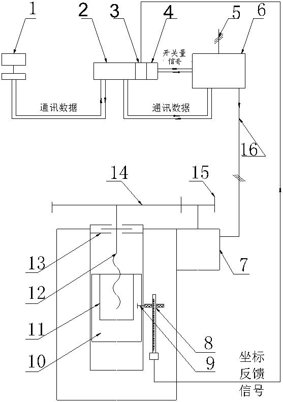
[0018] see figure 1 As shown, the figure shows the structure of a control system for an electric screw press provided by an embodiment of the present invention. For ease of description, only the parts related to the embodiment of the present invention are shown.

[0019] Such as figure 1 As shown, a control system for an electric screw press includes a main motor 7 that drives the slider 10 of the electric screw press to move linearly up and down, a PLC controller 2 that controls the operation of the main motor 7 and connects the main motor through a power cable 16 7, a motor driver 6 connected to the PLC controller 2 for setting and collecting data; also includes a slider position detection device 8 for detecting the current coordinate position of the slider 10;...


PUM


Abstract

The invention discloses an electric screw press control system and an electric screw press control method. The electric screw press control system comprises a main motor, a programmable logic controller (PLC), a motor driver, an upper computer and a sliding block position detection device, wherein the main motor drives a sliding block of an electric screw press to do linear motion and is not provided with a shaft end position sensor; the PLC and the motor driver control the operation of the main motor; the upper computer is connected with the PLC and used for setting and acquiring data; the sliding block position detection device is used for detecting the current coordinate position of the sliding block; the sliding block position detection device is connected with the PLC through an analog quantity module; and the motor driver is connected with the PLC through a data bus and a switch quantity signal. The current coordinate position of the sliding block is detected by the sliding block position detection device and fed back to the PLC, so that the state switching of the main motor can be controlled, the shut-down phenomenon caused by failure of the shaft end sensor is eliminated, the using reliability of the whole electric screw press is improved, and the service life of a die is prolonged.

Description

technical field [0001] The invention relates to the technical field of electric screw presses, in particular to an electric screw press control system and a control method. Background technique [0002] The electric screw press is a new type of screw press, which is widely used in the forging and forming industry. The main motion motor frequently rotates forward and reverse, and the slider is driven to and fro by the flywheel, screw and nut. Because the electric screw press has good energy saving, It has the characteristics of small starting current, good speed regulation, high operating efficiency and low noise, so the popularity rate has a tendency to increase year by year. [0003] The common main motor in the electrical system of the existing mainstream electric screw press in China, whether it is a permanent magnet synchronous motor, a switched reluctance motor or an AC servo motor, is equipped with a shaft end position sensor at the motor shaft end to feed back the col...

Claims


Application Information

Patent Timeline
Patent Type & Authority Applications(China)
IPC IPC(8): B21J9/20B30B15/26
Inventor 程贤勇赵至友耿孝富
Owner 青岛宏达锻压机械有限公司
Learn More