Solution regeneration device based on heat accumulating chamber low-temperature flue gas residual heat utilization

A solution regeneration, low temperature flue gas technology, applied in waste heat treatment, climate sustainability, lighting and heating equipment, etc. Ideal and other problems, to achieve the effect of low operation and maintenance cost, good thermal shock resistance and long service life

Inactive Publication Date: 2015-02-25
ANHUI UNIVERSITY OF TECHNOLOGY
View PDF2 Cites 0 Cited by
  • Summary
  • Abstract
  • Description
  • Claims
  • Application Information

AI Technical Summary

Problems solved by technology

However, the existing solution dehumidification technology often uses hot water generated by solar collectors as a regeneration heat source, and uses hot water to heat the solution through a partition heat exchanger to regenerate it. However, solar energy is discontinuous throughout the day, so it does not Suitable for continuous running processes in industry
Moreover, the hot water and the solution generated by the solar collector conduct heat transfer indirectly through the partition wall. There are many factors affecting the heat transfer, the heat transfer effect is not ideal, and the low-temperature flue gas waste heat of the industrial furnace cannot be recycled.
Moreover, even if the partition wall heat exchanger is used to recover the waste heat of the flue gas to heat the solution, the flue gas contains SO 2 , NO x and other gases that are likely to corrode the heat exchanger and shorten the service life

Method used


Image

  • Solution regeneration device based on heat accumulating chamber low-temperature flue gas residual heat utilization

Examples


Embodiment Construction

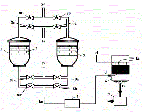
[0012] exist figure 1 Among them, the first regenerator 1 and the second regenerator 2 are installed in pairs; the flue gas inlet y i Divided into two paths, the flue gas inlet y i One of the passages is connected with the first valve 8a, the first valve 8a is connected with the second heat storage chamber 2, the second heat storage chamber 2 is connected with the second valve 8b, and the second valve 8b with flue gas outlet y o communicated, the flue gas inlet y i The other passage of is connected with the fifth valve 8e, the fifth valve 8e is connected with the first heat storage chamber 1, the first heat storage chamber 1 is connected with the sixth valve 8f, and the sixth valve 8f and smoke outlet y o connected.

[0013] air inlet k i Divided into two paths, the air inlet k i One of the passages is connected with the third valve 8c, the third valve 8c is connected with the first regenerator 1, the first regenerator 1 is connected wit...


PUM


Abstract

The invention discloses a solution regeneration device based on heat accumulation chamber low-temperature flue gas residual heat utilization, and belongs to the technical field of residual heat recycling. The device comprises a solution regenerator, a heat accumulating chamber, a concentrated solution groove, a heat accumulating body, a filter and a valve. The device recycles low-temperature flue gas residual heat emitted during industrial production process by utilizing a heat accumulating and heat transfer technology, and utilizes the low-temperature flue gas residual heat for heating air; air after temperature rising is in direct contact with the solution for transferring heat and media, so that the solution is regenerated; and the regenerated solution can be used for air blowing and dehumidification for an industrial kiln or fresh air dehumidification of an air conditioner. According to the invention, the heat accumulating chamber is adopted for recycling low-temperature flue gas residual heat, energy sources are saved, and the heat recovery efficiency is high, so that hot air is in direct contact with the solution for transferring heat and media, and the aims of intensifying the media transfer effect and improving heat transfer and media transfer efficiency can be realized.

Description

technical field [0001] The invention belongs to the technical field of waste heat recovery and utilization, and in particular relates to a solution regeneration device based on the utilization of low-temperature flue gas waste heat in a regenerator. Background technique [0002] In recent years, the solution dehumidification technology has been developed rapidly. The solution dehumidification system can be driven by a low-temperature heat source. It uses a salt solution with strong moisture absorption capacity to exchange heat and mass with humid air in a dehumidifier, thereby achieving the purpose of air dehumidification. , which overcomes the problems of high-grade energy consumption, high energy consumption and environmental pollution in freezing dehumidification. The dehumidifier and regenerator are the most important components of the solution dehumidification air conditioning system. The regenerator concentrates and regenerates the solution for continued use by the de...

Claims


Application Information

Patent Timeline
Patent Type & Authority Patents(China)
IPC IPC(8): B01D53/26F27D17/00
CPCY02P10/25Y02P80/15
Inventor 刘映辉黄志甲
Owner ANHUI UNIVERSITY OF TECHNOLOGY
Why Eureka
Try Eureka