
Analog multiplier in feedback loop of switching voltage regulator

A technology of switching voltage regulator and analog multiplier, which is applied in the direction of instruments, output power conversion devices, and adjustment of electric variables, etc., and can solve problems such as inaccurate compensation

Inactive Publication Date: 2013-03-27
苏州硅智源微电子有限公司
View PDF7 Cites 3 Cited by
  • Summary
  • Abstract
  • Description
  • Claims
  • Application Information

AI Technical Summary

Problems solved by technology

However, these feed-forward signals also have the disadvantage of
Problems encountered with these existing solutions include: imprecise compensation, small range of allowable input voltages, and switching frequency and jitter

Method used


Image

  • Analog multiplier in feedback loop of switching voltage regulator
  • Analog multiplier in feedback loop of switching voltage regulator

Examples


Embodiment Construction

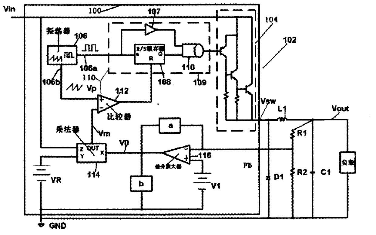
[0014] refer to figure 1 , a mobile device showing a monolithic integrated circuit voltage regulator in a switching regulator circuit 102 operating in a positive buck mode, the switching regulator device 100 is connected with discrete components. For example, while in figure 1 Not shown, device 100 preferably includes one or more terminals and circuitry to perform various functions, such as frequency compensation, current limiting, soft-start operation and shutdown. In addition, the functions of various circuits included in apparatus 100 may be implemented by alternate use of discrete components (eg, an additional switch or differential amplifier may be used).

[0015] exist figure 1 , the four terminals of device 100 are shown, including the terminal for input power (V in ), a switch output terminal (V sw ), feedback terminal (FB) and ground terminal (GND). Terminal V in A connection point for an input voltage is provided and used to provide power to the internal circui...


PUM


Abstract

The invention provides an analog multiplier in a feedback loop of a switching voltage regulator. The analog multiplication feed-forward technology is used in the feedback loop of the switching voltage regulator. When input voltage of the voltage regulator is changed, the analog multiplier does not need to change voltage by connecting the output end of an error amplifier to a voltage regulator circuit and enables loop gain to be irrelevant to the input voltage.

Description

technical field [0001] Switching regulators, like all feedback systems, must be properly "compensated" to ensure that the feedback loop does not oscillate. Compensation is particularly difficult in switching regulators because inductors and resistors (in the LC filter network) are often used to invert the switching waveform to obtain a regulated DC output voltage, causing large phase shifts in the early part of the feedback loop. shift. Also, the "gain" of the loop is usually a function of the DC input voltage. When the input voltage varies over a wide range, it will cause instability problems or low loop response. [0002] Another problem with switching regulators is slow response to sudden changes in input voltage or load current. The regulator has a high DC gain, which enables it to maintain a well-regulated output with large changes in input voltage and load current, but if these changes are rapid, there will be large transient output voltage changes, while The feedbac...

Claims


Application Information

Patent Timeline
IPC IPC(8): H02M3/157
Inventor 包兴坤
Owner 苏州硅智源微电子有限公司
Learn More